Vapor chamber

Pending Publication Date: 2020-10-01
AURAS TECH
View PDF0 Cites 0 Cited by
  • Summary
  • Abstract
  • Description
  • Claims
  • Application Information

AI Technical Summary

Benefits of technology

The present invention provides a vapor chamber with a fixing frame that helps manufacturers or users easily assemble and fix the chamber on a supporting plate with a heat source. The fixing frame also minimizes the possibility of the chamber getting deformed.

Problems solved by technology

However, the slim-type vapor chamber is readily suffered from deformation.

Method used


Image

  • Vapor chamber
  • Vapor chamber
  • Vapor chamber

Examples


Embodiment Construction

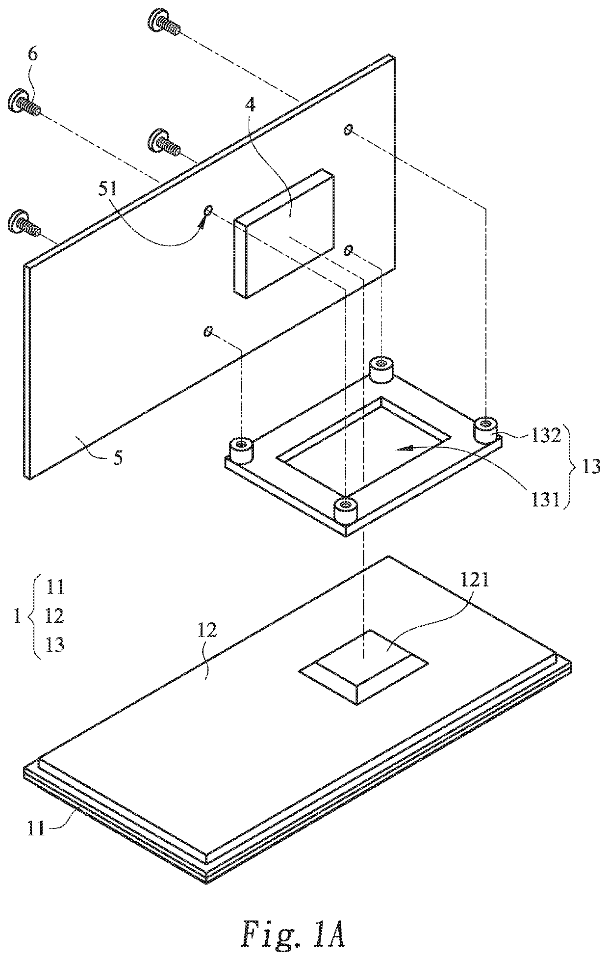
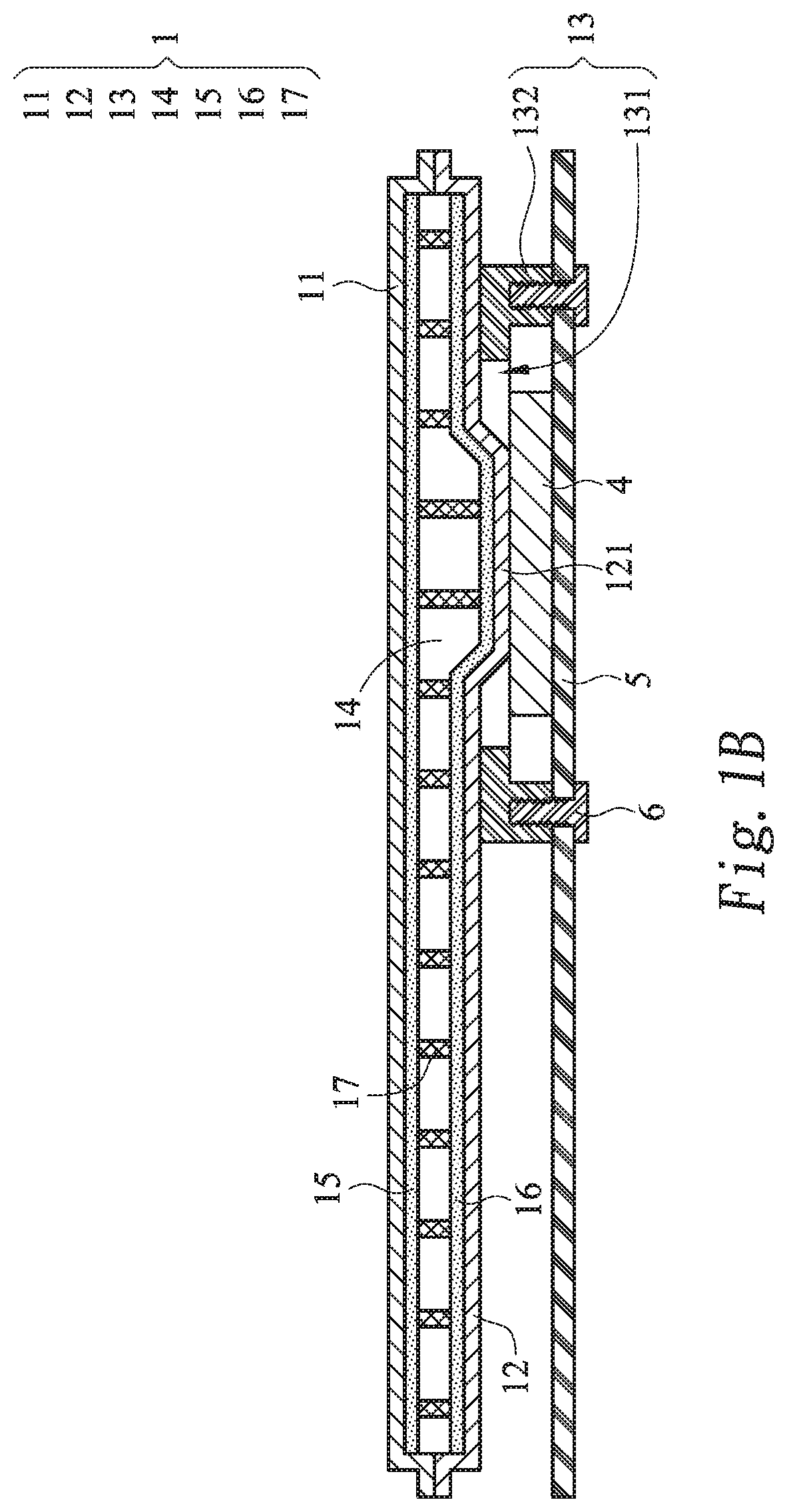
[0040]Please refer to FIGS. 1A and 1B. FIG. 1A is a schematic exploded view illustrating a vapor chamber and a supporting plate according to a first embodiment of the present invention. FIG. 1B is a schematic cross-sectional view illustrating the vapor chamber and the supporting plate according to the first embodiment of the present invention.

[0041]In this embodiment, the vapor chamber 1 comprises an upper plate 11, a lower plate 12 and a fixing frame 13. The vapor chamber 1 is in thermal contact with at least one heat source 4. The heat source 4 is fixed on a supporting plate 5. After the upper plate 11 and the lower plate 12 of the vapor chamber 1 are attached on each other, a working space 14 is defined. In the working space 14, a first capillary structure 15 is formed on an inner surface of the upper plate 11, and a second capillary structure 16 is formed on an inner surface of the lower plate 12. Moreover, a support structure 17 is clamped between the upper plate 11 and the low...


PUM


Abstract

A vapor chamber includes an upper plate, a lower plate and a fixing frame. The lower plate is attached on the upper plate. The lower plate includes a raised structure. The fixing frame is attached on the lower plate. The fixing frame includes a hollow portion and at least one fastening part. The raised structure is accommodated within the hollow portion. The fixing frame is helpful for facilitating the manufacturer or the user to directly assemble and fix the vapor chamber on a supporting plate with a heat source. Moreover, due to the fixing frame, the possibility of causing deformation of the vapor chamber is minimized.

Description

FIELD OF THE INVENTION[0001]The present invention relates to a heat dissipation device, and more particularly to a vapor chamberBACKGROUND OF THE INVENTION[0002]A vapor chamber is one of the heat dissipation devices. Generally, a heat source is fixed on a supporting plate, and a lower plate of the vapor chamber is attached on the heat source. However, the slim-type vapor chamber is readily suffered from deformation. It is important to securely fix the heat source on the supporting plate and attach the lower plate of the vapor chamber on the heat source while avoiding deformation of the vapor chamber.[0003]Moreover, it is also important to quickly and easily fix the final product of the vapor chamber on the heat source.SUMMARY OF THE INVENTION[0004]For solving the drawbacks of the conventional technologies, the present invention provides a vapor chamber with a fixing frame. The fixing frame is helpful for facilitating the manufacturer or the user to directly assemble and fix the vapo...

Claims


Application Information

Patent Timeline
IPC IPC(8): F28D15/04
CPCF28D15/043F28D15/0233F28F3/12
Inventor CHANG, TIEN-YAOKUO, CHE-WEI
Owner AURAS TECH
Why Eureka
Try Eureka