Agitator for treating organic waste

a technology of organic waste and agitator, which is applied in the direction of biochemical equipment and processes, transportation and packaging, rotary stirring mixers, etc., can solve the problems of difficult selection of landfills, food waste generally has undesirable effects on the growth of crops, and bad smell, etc., to achieve maximum microorganism activity, remove food waste, and remove food waste

Inactive Publication Date: 2010-06-03
KWON SANGDONG
View PDF2 Cites 4 Cited by
  • Summary
  • Abstract
  • Description
  • Claims
  • Application Information

AI Technical Summary

Benefits of technology

[0020]As described above, according to the aspect of the present invention, it is possible to allow organic materials to uniformly circulate in the agitation vessel by appropriately setting the positions and shapes of the agitating blades and the auxiliary agitating blade. Therefore, it is possible to maximize the activity of the microorganisms. As a result, it is possible to remove food waste by fermenting the food waste or to change livestock waste into manure in a short period of time.
[0021]The agitator according to the aspect of the present invention can remove food waste by gasifying the food waste in a short period of time. For this reason, the agitator can be used as a device for significantly reducing food waste in homes, eating houses, restaurants, and the like.

Problems solved by technology

If the food waste is buried in the ground, environmental pollution is caused by the burial of the food waste for a long time and a bad smell is generated.
Therefore, bad smell control facilities should be provided, and it is difficult to select landfills.
Further, when the food waste is recycled as manure, the food waste generally has undesirable effects on the growth of crops and pollutes the soil because a large amount of salt is contained in the food waste in the case of Korea.
Unless the organic materials uniformly circulate, microorganisms supplied to facilitate fermentation do not act well.

Method used


Image

  • Agitator for treating organic waste
  • Agitator for treating organic waste
  • Agitator for treating organic waste

Examples


Embodiment Construction

[0027]A preferred embodiment of the present invention will be described in detail below. However, the embodiment is only illustrative, and may have various modifications within the scope and spirit of the invention. Further, the present invention is not limited to the embodiment.

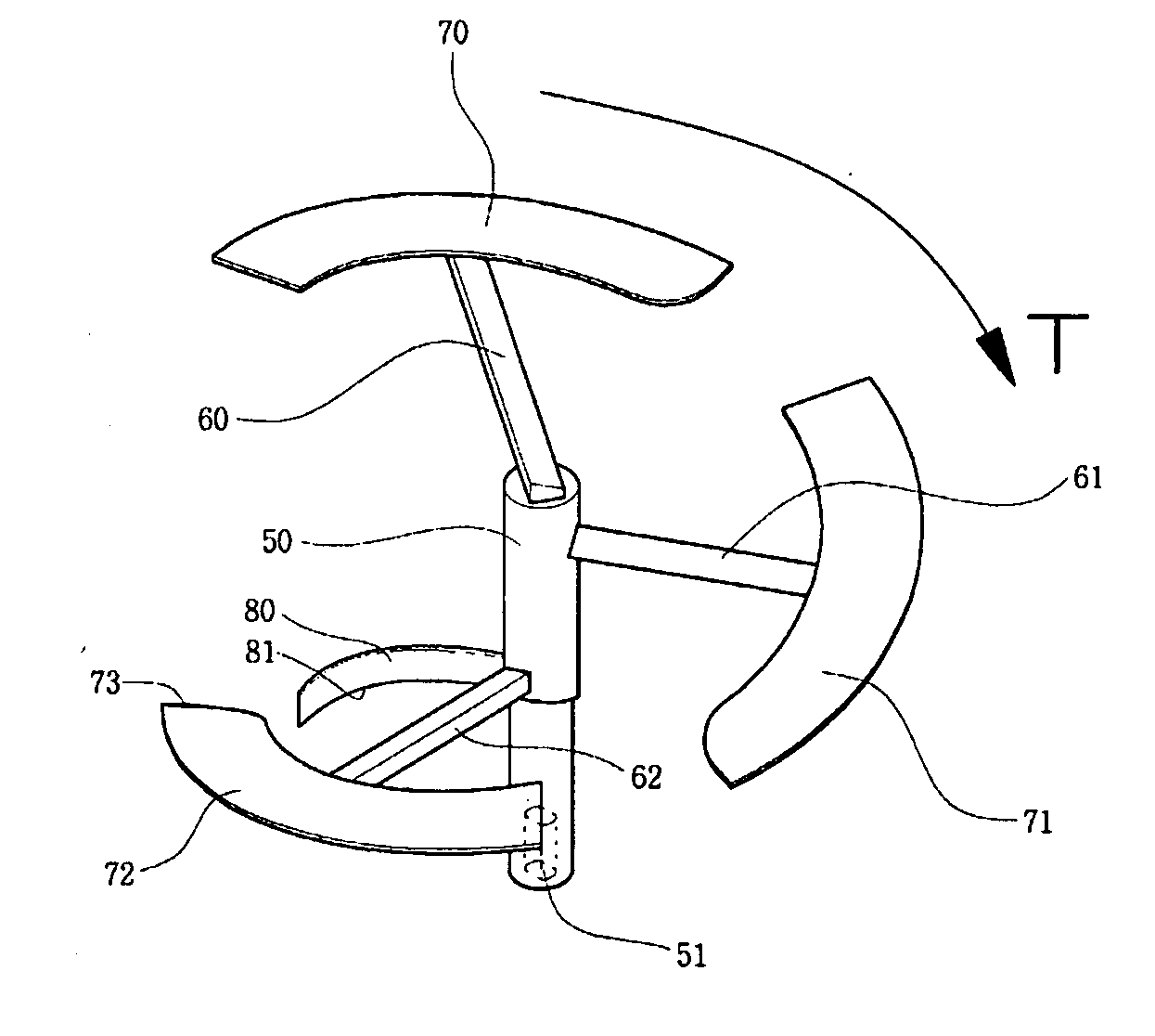
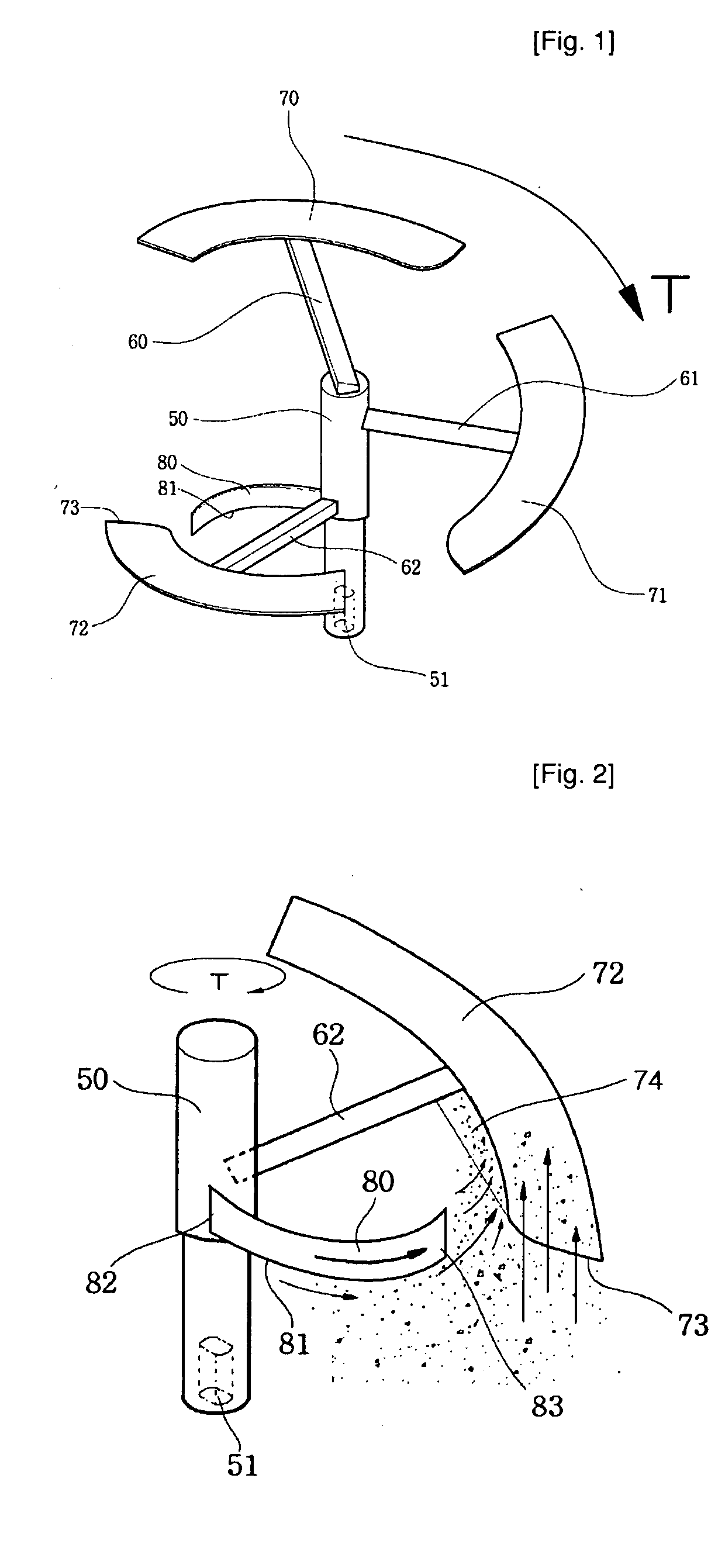
[0028]FIG. 1 is a perspective view of an agitator according to an embodiment of the present invention, and FIG. 2 is a view showing the movement of contents while the contents are agitated in the agitator according to the embodiment of the present invention.

[0029]As shown in the drawings, an agitator according to the embodiment of the present invention is used to treat food waste. The agitator includes a rotating shaft 50, connecting members 60, 61, and 62, agitating blades 70, 71, and 72, and an auxiliary agitating blade 80.

[0030]The rotating shaft 50 is a rod-shaped member that is made of stainless steel and extends in a longitudinal direction. A groove 51 to which a shaft of a drive motor is fitted is for...


PUM


Abstract

The present invention provides an agitator that uniformly mixes contents in an agitation vessel through rotation. The agitator includes a rotating shaft, a plurality of connecting members, a plurality of agitating blades, and an auxiliary agitating blade. One end of the rotating shaft is connected to a driving unit. Each of the connecting members has a predetermined length, and one ends of the connecting members are fixed to the rotating shaft at different positions in a longitudinal direction of the rotating shaft. The plurality of agitating blades arc fixed to the other ends of the plurality of connecting members, respectively, so as to be inclined downward. The auxiliary agitating blade has the shape of a strip curved at a predetermined angle. One end of the auxiliary agitating blade is fixed to the rotating shaft or the connecting member, and the other end thereof is disposed inside the agitating blade near a lower side of one of the agitating blades with a predetermined distance therebetween.

Description

TECHNICAL FIELD [0001]The present invention relates to an agitator that allows contents to uniformly circulate in an agitation vessel, and more particularly, to an agitator for treating organic waste that can perform a removal of food waste by not burning the food waste but decomposing the food waste using fermentation thereof or change livestock waste into manure by the fermentation of the livestock waste very short period of time.BACKGROUND ART [0002]A method of burying organic waste, particularly, food waste, which is generated from homes or eating houses, in the ground, and a method of recycling food waste as manure by a separate food waste treating apparatus have been considered. If the food waste is buried in the ground, environmental pollution is caused by the burial of the food waste for a long time and a bad smell is generated. Therefore, bad smell control facilities should be provided, and it is difficult to select landfills.[0003]Further, when the food waste is recycled a...

Claims


Application Information

Patent Timeline
Patent Type & Authority Applications(United States)
IPC IPC(8): B01F7/00
CPCB01F7/00141B01F7/00158C12M27/02B01F7/00641B09B3/00B01F7/00275B01F27/0724B01F27/0726B01F27/1123B01F27/192Y02W30/40
Inventor KWON, SANGDONG
Owner KWON SANGDONG
Why Eureka
Try Eureka