

Clipping prevention device and clipping prevention method
a technology of clipping prevention and clipping, which is applied in the direction of volume compression/expansion, volume compression/expansion in untuned/low-frequency amplifiers, instruments, etc., can solve the problems of user discomfort, inability to gain control at a faster rate, etc., to prevent the clipping of analog audio signals amplified or attenuated, and to achieve fast gain control. , the effect of preventing the clipping of the analog audio signal
- Summary
- Abstract
- Description
- Claims
- Application Information
AI Technical Summary
Benefits of technology
Problems solved by technology
Method used
Image

Examples
first embodiment
1. First Embodiment
1-1. Configuration of the Car Audio Device
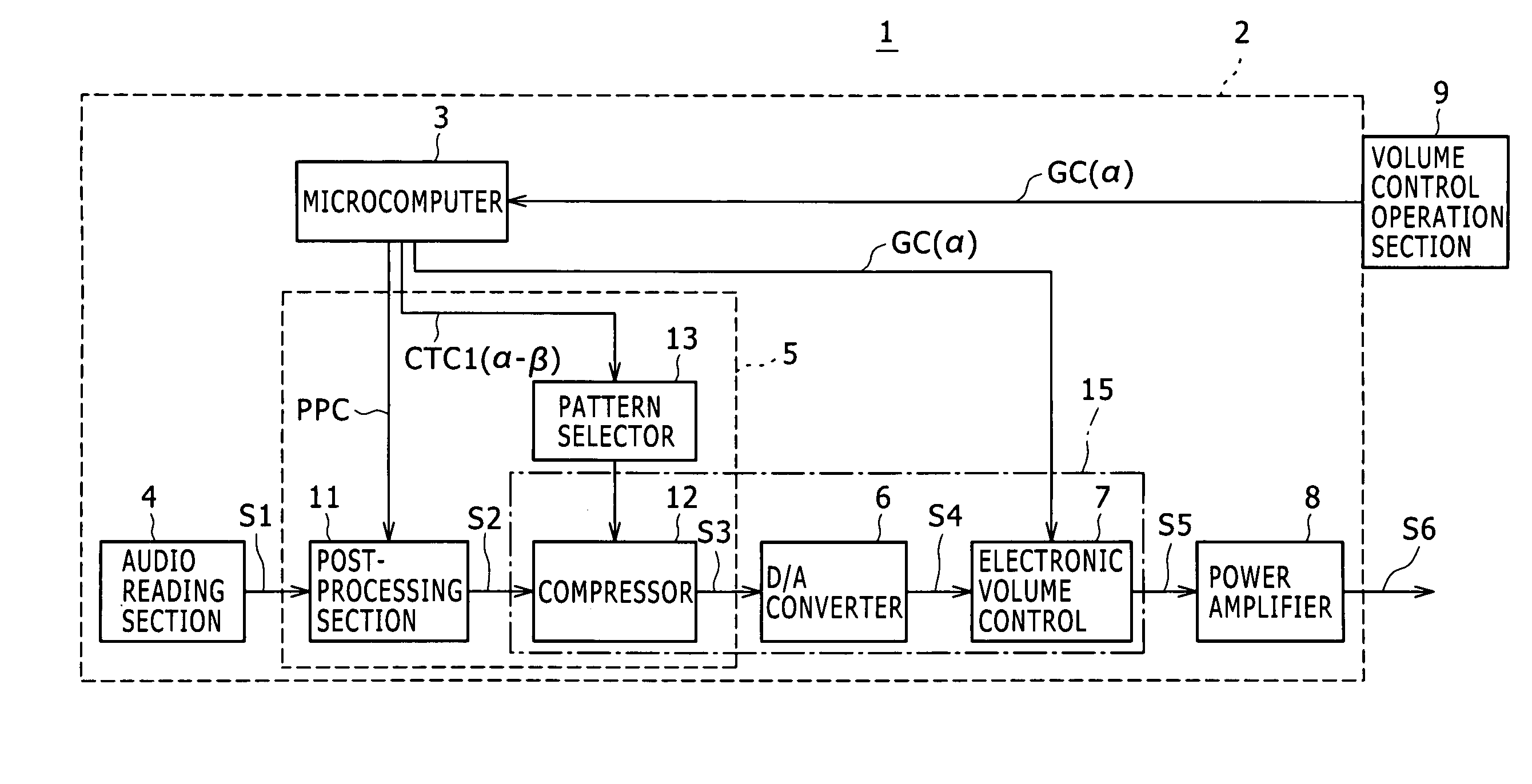
[0043]As illustrated in FIG. 1, a car audio device 1 is powered by a battery of about 12 V (not shown).
[0044]At this time, a microcomputer 3, audio reading section 4, DSP (Digital Signal Processor) 5 and D / A (Digital-to-Analog) converter 6 of the car audio device 1 are designed to operate, for example, at about 3.3 V for power saving purposes. On the other hand, an electronic volume control 7 of the same device 1 is designed to operate at about 10 V, and a power amplifier 8 thereof at about 12 V. Incidentally, we assume that the operating voltage of the power amplifier 8 of the car audio device 1 remains unchanged.
[0045]A volume control operation section 9 includes, for example, a rotatable operator provided on the front side of a body section 2 and accepts the user's rotation of the operator.
[0046]The microcomputer 3 is provided in the body section
[0047]2. The microcomputer 3 includes a CPU (Central Processing Unit), ROM ...
second embodiment
2. Second Embodiment
2-1. Configuration of the Car Audio Device
[0127]As illustrated in FIG. 11 in which like components as those in FIG. 1 are denoted by the same reference symbols, a car audio device 20 according to a second embodiment has a DSP 30 rather than the DSP 5 provided in the first embodiment. Incidentally, we assume that the operating voltage of the power amplifier 8 of the car audio device 20 remains unchanged.
[0128]The DSP 30 includes the post-processing section 11, a compressor unit 31 and a gain setting section 32. An amplification unit 35 includes a variable digital volume control (+) 33, the compressor 12, a variable digital volume control (−) 34, the D / A converter 6 and the electronic volume control 7.
[0129]To reproduce music content stored in a medium such as a CD or external USB memory, the car audio device 20 uses the audio reading section 4 to read the digital audio signal S1 of the music content. Then, the audio reading section 4 outputs the digital audio sign...
third embodiment
3. Third Embodiment
3-1. Configuration of the Car Audio Device
[0189]As illustrated in FIG. 17 in which like components as those in FIG. 11 are denoted by the same reference symbols, a car audio device 40 according to a third embodiment has resistors 42 and 43 in addition to the components of the car audio device 20 according to the second embodiment.
[0190]The resistor 42 is, for example, 30 kΩ and has one of its terminals connected to the power amplifier 8 and the other terminal connected in series to the resistor 43. The resistor 43 is, for example, 10 kΩ and has its terminal, which is not connected to the resistor 42, grounded. A connection point P between the resistors 42 and 43 is connected to the microcomputer 3.
[0191]To reproduce music content stored in a medium such as a CD or external USB memory, the car audio device 40 uses the audio reading section 4 to read the digital audio signal S1 of the music content. Then, the audio reading section 4 outputs the digital audio signal ...
PUM
 Abstract
Description
Claims
Application Information