Multi-piece punctal plug

a punctal plug and multi-piece technology, applied in the field of ophthalmology, can solve the problems of recurring problems in the retention of the plug over tim

Active Publication Date: 2010-06-03
ORDICH STEVEN
View PDF9 Cites 6 Cited by
  • Summary
  • Abstract
  • Description
  • Claims
  • Application Information

AI Technical Summary

Problems solved by technology

Although the use of punctal plugs to deliver a drug to the eye, or to the body, or for other purposes, is known, retention of the plugs over time continues to be problematic since the plugs tend to fall out prematurely.

Method used


Image

  • Multi-piece punctal plug
  • Multi-piece punctal plug
  • Multi-piece punctal plug

Examples


Embodiment Construction

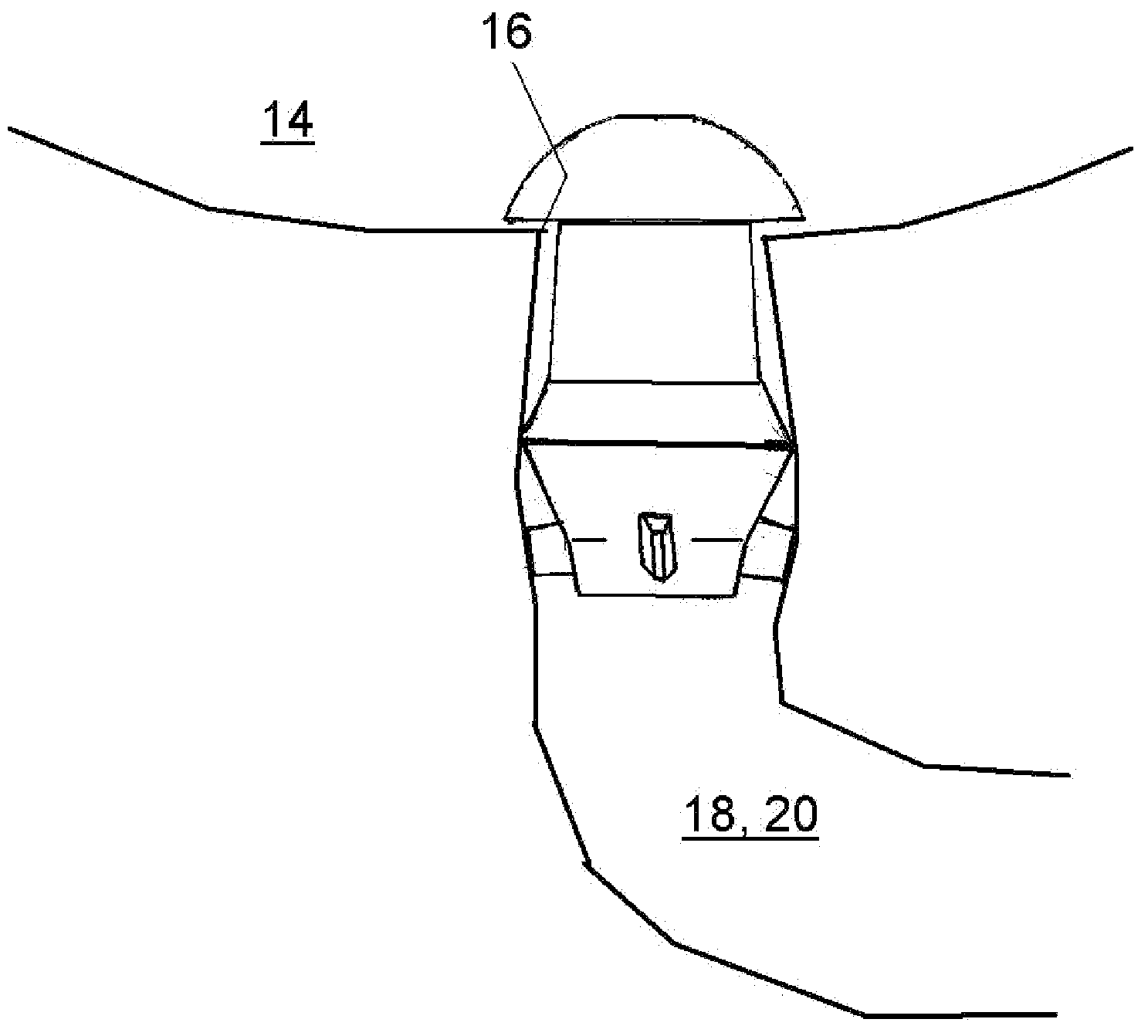
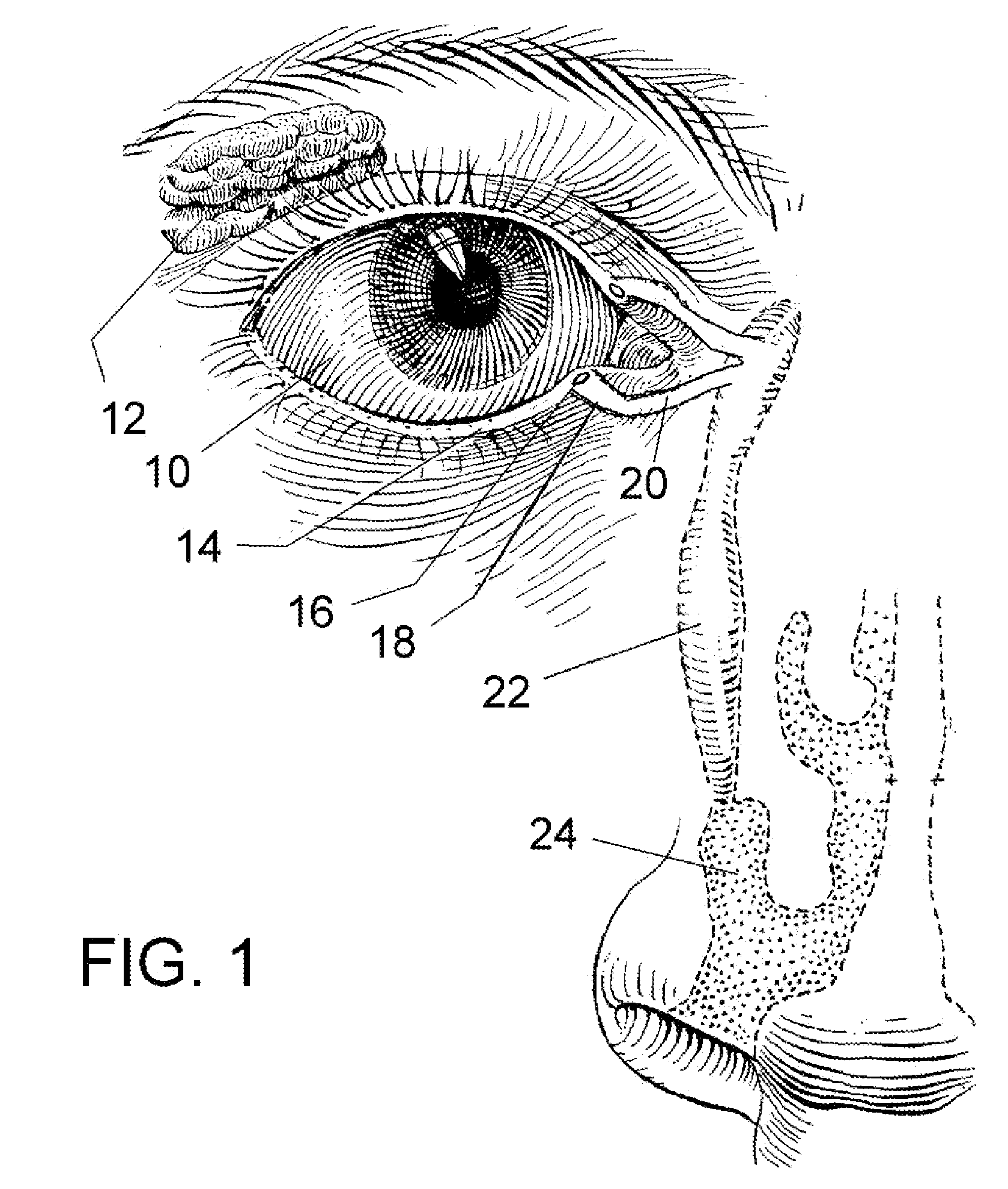
[0021]Referring now to the drawings, in which like reference numerals are used to refer to the same or similar elements, FIG. 1 shows the eye and nose area of a patient who would benefit from the punctal plug arrangement of the present invention. To better understand the environment in which the invention will operate, the patient is shown to have an eye 10 above which are located lacrimal glands 12 for producing tears. The tears will wet and coat the eye and will eventually move to the upper and lower lid margins 14 and then be channeled to the upper and lower punctum 16. The tears will then travel along the upper and lower canaliculus 18 and lacrimal ducts 20 (collectively referred to here simply as the lacrimal ducts), into the nasolacrimal duct 22 and then to the nasal cavity 24.

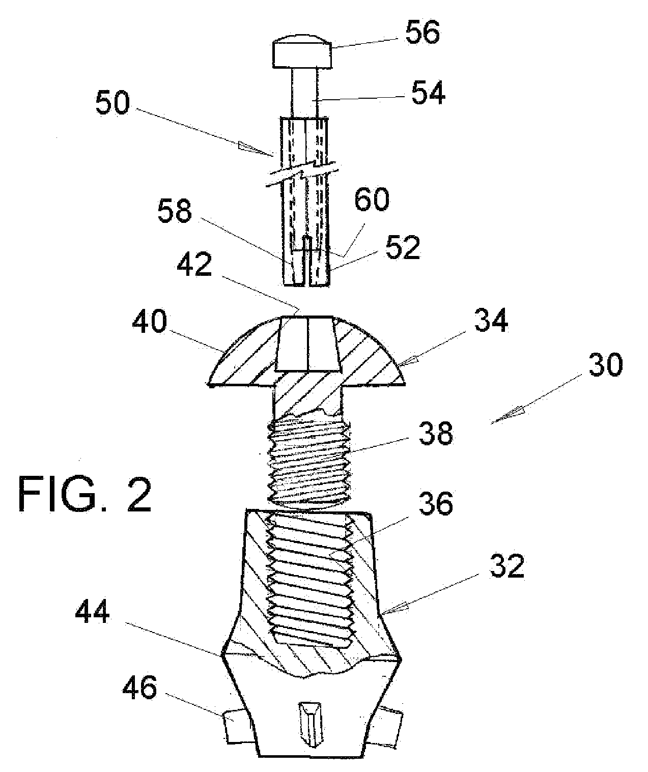
[0022]Referring now to FIGS. 2 and 3, a punctal plug arrangement 30 of the present invention is received in one of the lacrimal ducts 18, 20, at or near the corresponding lacrimal punctum 16 of a patient...


PUM


Abstract

A multi-piece punctal plug has one or more superficial plugs connected to an anchor plug deeper in the naso-lacrimal canaliculus. The anchor is fixed to the wall of the lacrimal duct while the superficial plugs are axially and detachably secured to the anchor plug so that the multi-plug complex may be inserted or removed together as one, or the superficial plugs may be detached separately and replaced securely without disturbing the anchor. Removal and insertion is accomplished by a specific tool having an end for engaging the plugs.

Description

FIELD AND BACKGROUND OF THE INVENTION[0001]The present invention relates generally to the field of ophthalmology, and in particular to a new and useful punctal plug that is made up of multiple parts to enhance its effectiveness.[0002]US Patent Application 2005 / 0232972 to the same inventor as the present application, is incorporated here by reference, and discloses a method and an apparatus for administering an active agent to a subject by applying the active agent to at least one surface of an ocular implant such as a punctal plug, and installing the implant, e.g. inserting the punctal plug into a punctal aperture of the subject.[0003]Although the use of punctal plugs to deliver a drug to the eye, or to the body, or for other purposes, is known, retention of the plugs over time continues to be problematic since the plugs tend to fall out prematurely.SUMMARY OF THE INVENTION[0004]It is accordingly an object of the present invention to overcome the retention problem of current punctal...

Claims


Application Information

Patent Timeline
Patent Type & Authority Applications(United States)
IPC IPC(8): A61F9/00
CPCA61F9/00772
Inventor ODRICH, STEVEN
Owner ORDICH STEVEN
Why Eureka
Try Eureka