Compliant Interbody Fusion Device With Deployable Bone Anchors

a fusion device and bone anchor technology, applied in the field of spine stabilization devices, can solve the problems of instability in the vertebrae, instability in the spine, and static size, and achieve the effect of reducing the risk of fracture, and reducing the stability of the bone anchorag

Active Publication Date: 2010-06-03
CUSTOM SPINE INC
View PDF6 Cites 22 Cited by
  • Summary
  • Abstract
  • Description
  • Claims
  • Application Information

AI Technical Summary

Benefits of technology

[0007]In view of the foregoing, an embodiment herein provides an interbody fusion implant with deployable bone anchors including a support member having a first end and a second end, the second end including two flanges, the flanges are configured to dig into an endplate of a vertebral body. The in

Problems solved by technology

A problem with the conventional spinal fusion implants is that they are static in size.
This poses various problems with their use and/or implantation.
As a result, nerves may become pinched, causing pain that radiates into other parts of the body and instability in the vertebrae.
This disrupts the normal biomechanics of the spine while correcting the instability.
Fusion, while correcting the instability, can also cause adjacent disc disease.
Also, generally the conventional

Method used


Image

  • Compliant Interbody Fusion Device With Deployable Bone Anchors
  • Compliant Interbody Fusion Device With Deployable Bone Anchors
  • Compliant Interbody Fusion Device With Deployable Bone Anchors

Examples


first embodiment

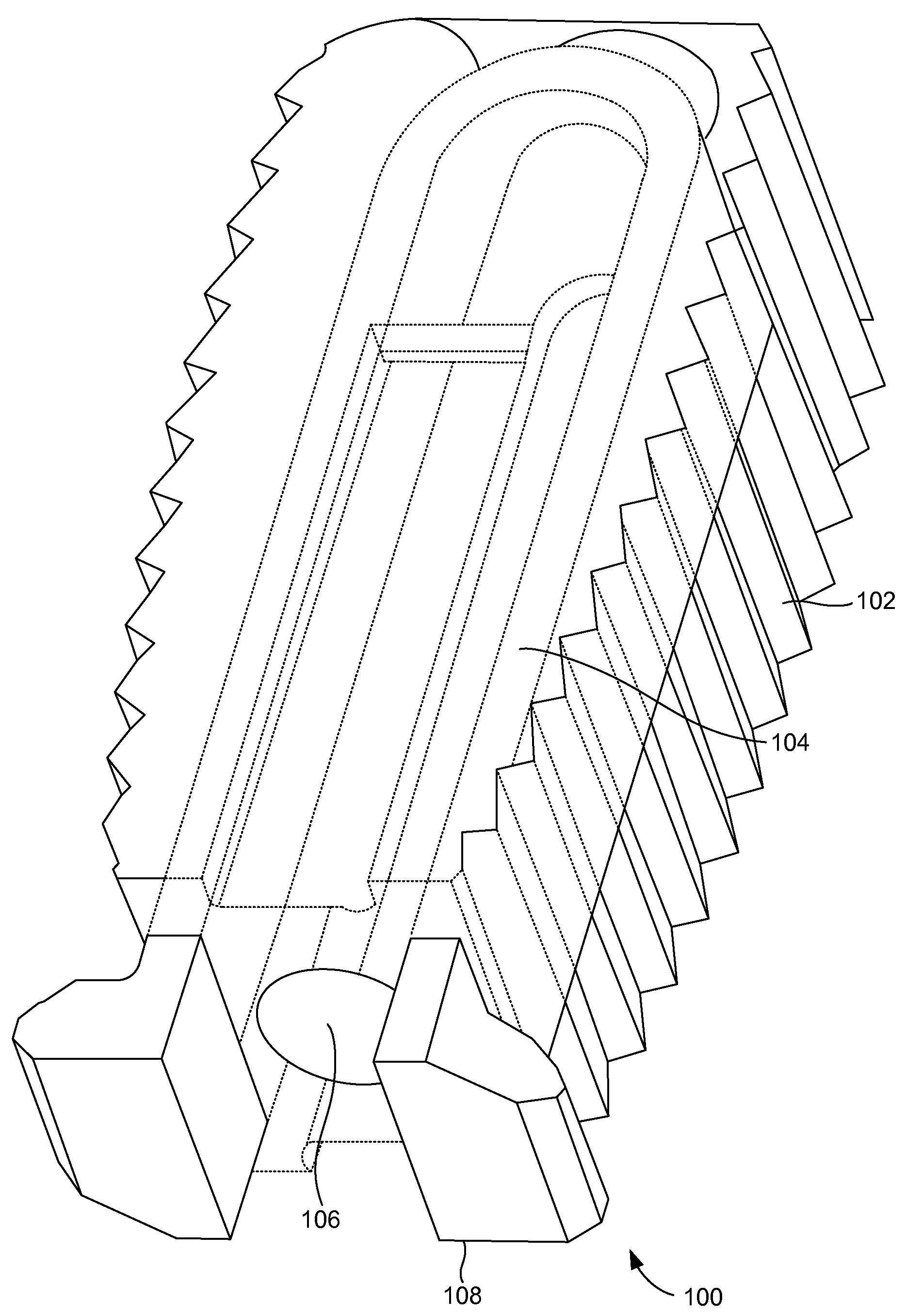
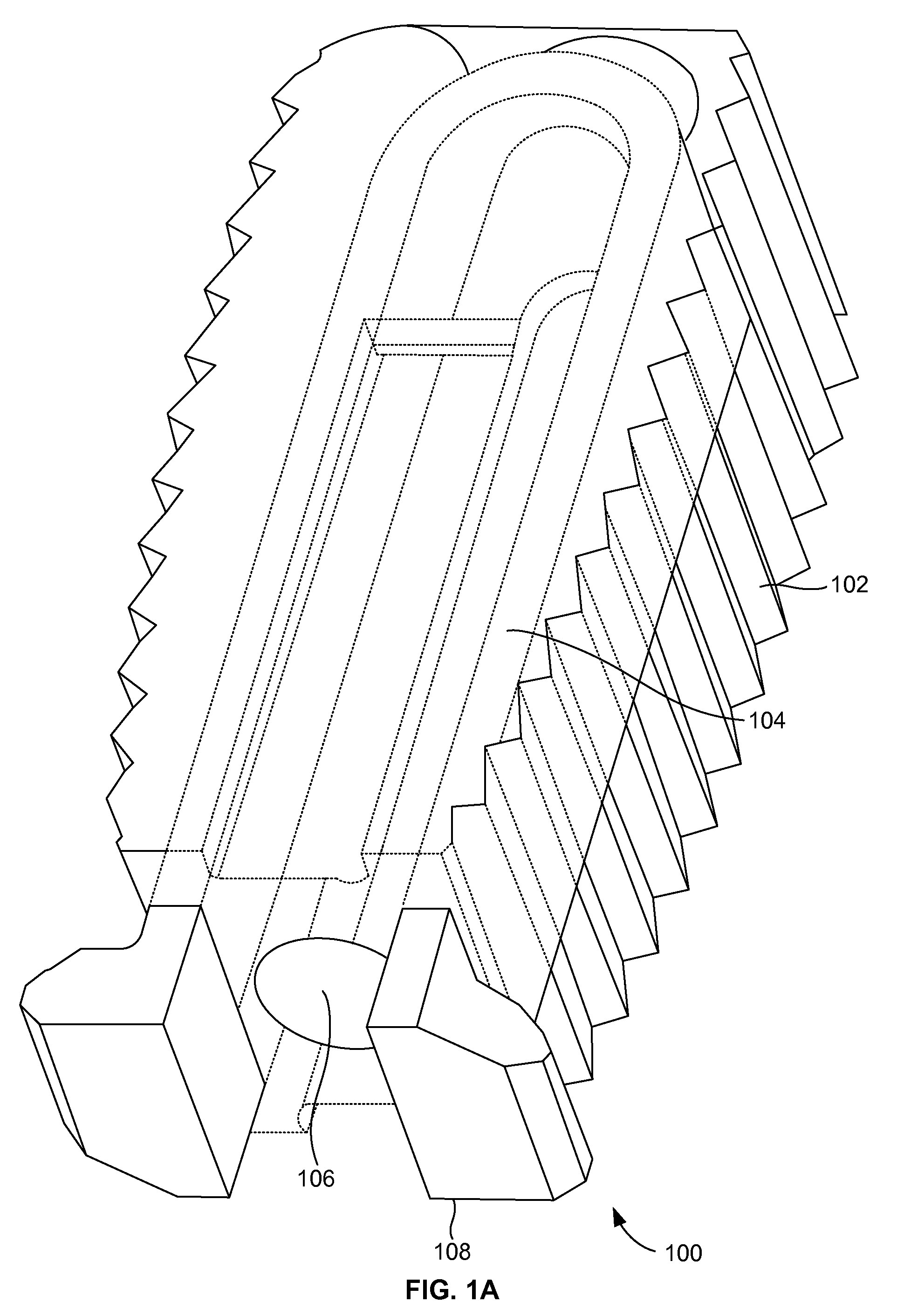
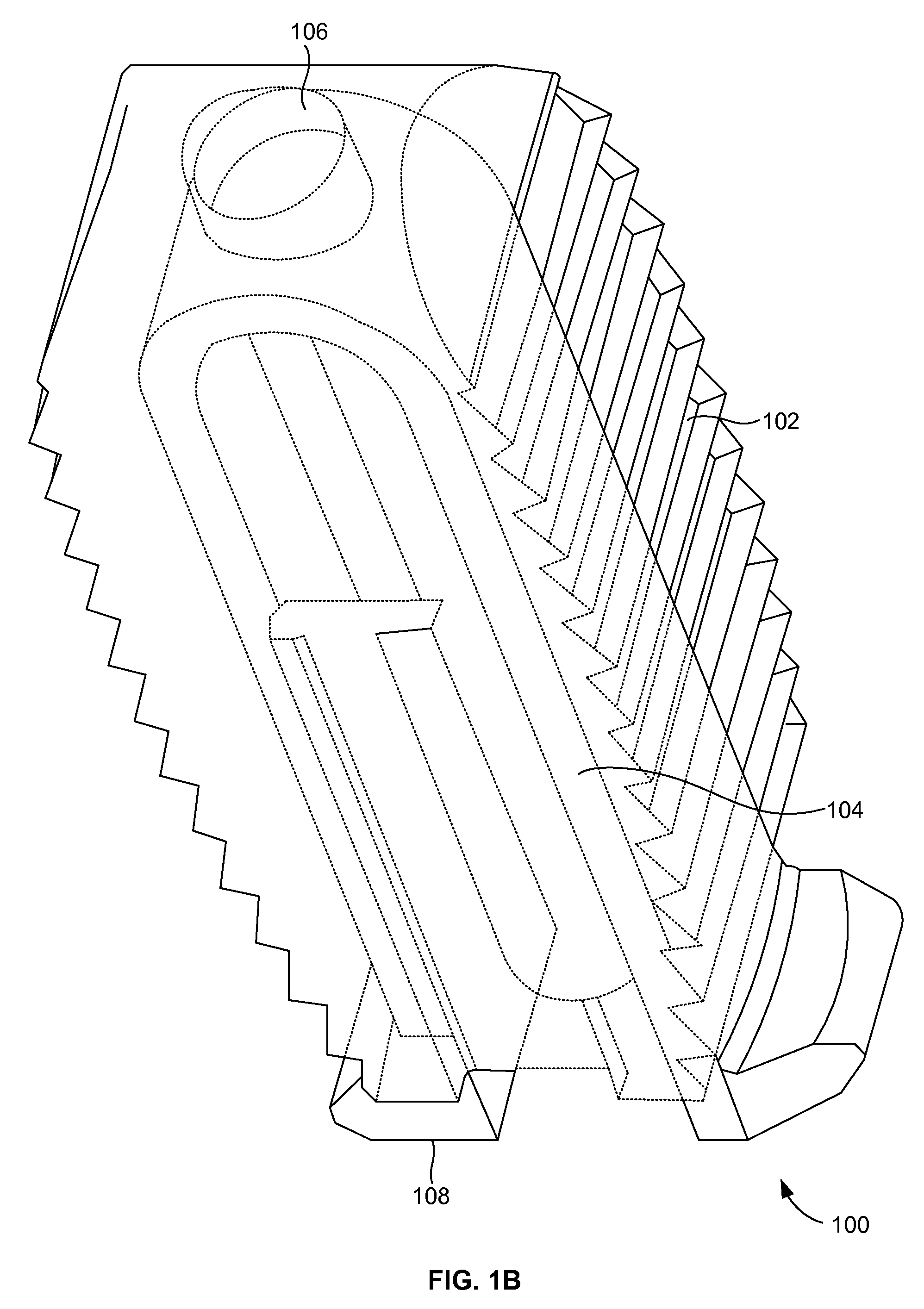
[0026]FIGS. 1A and 1B illustrate a perspective view of a compliant monolithic spinal fusion implant 100 herein. With reference to FIGS. 1A and 1B, the compliant monolithic spinal fusion implant 100 includes a compliant monolithic body 102, a support member 104, a longitudinal hole 106 along the vertical length of the support member 104, and flanges 108 located near the opening of the hole 106. The compliant monolithic spinal fusion implant 100 may be inserted anteriorly, posteriorly, or transforaminal in between vertebral bodies of the spine.

[0027]The longitudinal hole 106 along the vertical length of the clip shaped support member 104 enables the support member 104 to sustain a heavy load and flex freely. A cephalad and a caudal surface of the compliant monolithic spinal fusion implant 100 may be molded with a surface finish (e.g., teeth, geometry, or serrations) to provide an additional fixation with endplates (not shown). In one embodiment, the support member 104 is embodied as ...

second embodiment

[0030]FIGS. 2A and 2B illustrate a perspective view of a compliant monolithic spinal fusion implant 200 herein. The compliant monolithic spinal fusion implant 200 includes a compliant monolithic body 202, a support member 204, a longitudinal hole 206 along the vertical length of the I-shaped support member 204, and flanges 208. The support member 204 may allow more rigidity and support through the middle of the support member 204 which acts as a living-hinge in flexion-extension.

[0031]In one embodiment, the support member 204 is an I-shaped support member. The support member 204 may also be cut in both the front and side planes to allow two degrees of freedom, acting as a joint that can bend in both the sagital and transverse planes. The longitudinal hole 206 along the vertical length of the support member 204 may enable the support member 204 to sustain a heavy load and flex freely. The flanges 208 on the end of the support member 204 may dig into endplates (not shown) to provide ...

third embodiment

[0032]FIGS. 3A and 3B illustrate a perspective view of a compliant monolithic spinal fusion implant 300 herein. The compliant monolithic spinal fusion implant 300 includes a compliant monolithic body 302, a rod 304 longitude to the compliant monolithic body 302 with a plurality of symmetric spikes 306, and windows 308. The rod 304 is insert-molded in the compliant monolithic body 302. The spikes 306 are attached to the rod 304 perpendicular to the main axis of the rod 304.

[0033]The windows 308 are molded in the compliant monolithic body 302 to enable the rod 304 to rotate from a horizontal to a vertical configuration. In the vertical configuration, the spikes 306 penetrate the end plates (not shown) to fix the compliant monolithic body 302 in place. The rod 304 may be rotated with an appropriate driving instrument (not shown).


PUM


Abstract

An interbody fusion implant with deployable bone anchors includes a support member, a monolithic body that accommodates the support member, and a longitudinal hole along a vertical length of the support member. The support member includes a first end and a second end. The second end includes two flanges. The flanges are configured to dig into an endplate of a vertebral body. The flanges of the support member provide a location fixation on an implantation of the interbody fusion implant into the vertebral body. The support member may also include at least one of a clip shaped support member and an I-shaped support member. The I-shaped support member may allow a rigidity and a support in flexion-extension through a living-hinge positioned in a middle of the I-shaped support member. The longitudinal hole sustains loads imported on the interbody fusion implant and allows the interbody fusion implant to flex freely.

Description

BACKGROUND[0001]1. Technical Field[0002]The embodiments herein generally relate to spinal stabilization devices, and more particularly to a compliant interbody fusion device with deployable bone anchors.[0003]2. Description of the Related Art[0004]Conventional spinal fusion implants typically having projections that can be deployed after the implant has been inserted into the disc space and are used to stabilize the human spine. A problem with the conventional spinal fusion implants is that they are static in size. This poses various problems with their use and / or implantation. As a result, nerves may become pinched, causing pain that radiates into other parts of the body and instability in the vertebrae.[0005]To overcome this, spinal decompression and fusion procedures can be augmented with bone or implants being inserted between the vertebral bodies and held in place with pedicle screws. This disrupts the normal biomechanics of the spine while correcting the instability. Fusion, w...

Claims


Application Information

Patent Timeline
IPC IPC(8): A61F2/44A61B17/70A61B17/04
CPCA61F2/447A61F2220/0033A61F2002/30364A61F2002/30476A61F2002/30523A61F2002/30576A61F2002/30579A61F2002/30598A61F2002/30772A61F2002/30841A61F2002/30904A61F2002/4475A61F2002/4627A61F2220/0025A61F2/4611A61F2002/30593A61F2002/30594
Inventor MARKWORTH, AARON D.OH, YOUNG HOONABDELGANY, MAHMOUD F.
Owner CUSTOM SPINE INC
Why Eureka
Try Eureka