Riveting unit for electric rivet gun

a technology of electric rivet gun and riveting unit, which is applied in the direction of metal-working machine components, manufacturing tools, and forming safety devices, etc., can solve problems such as the breakdown of the riveting uni

Active Publication Date: 2010-06-10
TRANMAX MACHINERY
View PDF4 Cites 18 Cited by
  • Summary
  • Abstract
  • Description
  • Claims
  • Application Information

AI Technical Summary

Benefits of technology

[0006]It is one objective of the present invention to provide a riveting unit for an electric rivet gun that has a sensor to detect the movement of a clamping jaw for ensuring the normal operation of the electric rivet gun.
[0008]Once the locating portion of the clamping jaw is moved from the first position to the second position, the second sensor can allow the transmission unit to stop the movement of the clamping jaw for preventing excessive backward movement of the clamping jaw and ensuring normal operation of the riveting unit.

Problems solved by technology

However, the operation time of the driving unit is decided by holding the trigger, that is to say, if a user presses the trigger too short, the blind rivet can't be ejected, and if the user presses the trigger too long, the clamping jaw may be locked induced by its excessive backward movement, causing the breakdown of the riveting unit.

Method used


Image

  • Riveting unit for electric rivet gun
  • Riveting unit for electric rivet gun
  • Riveting unit for electric rivet gun

Examples


Embodiment Construction

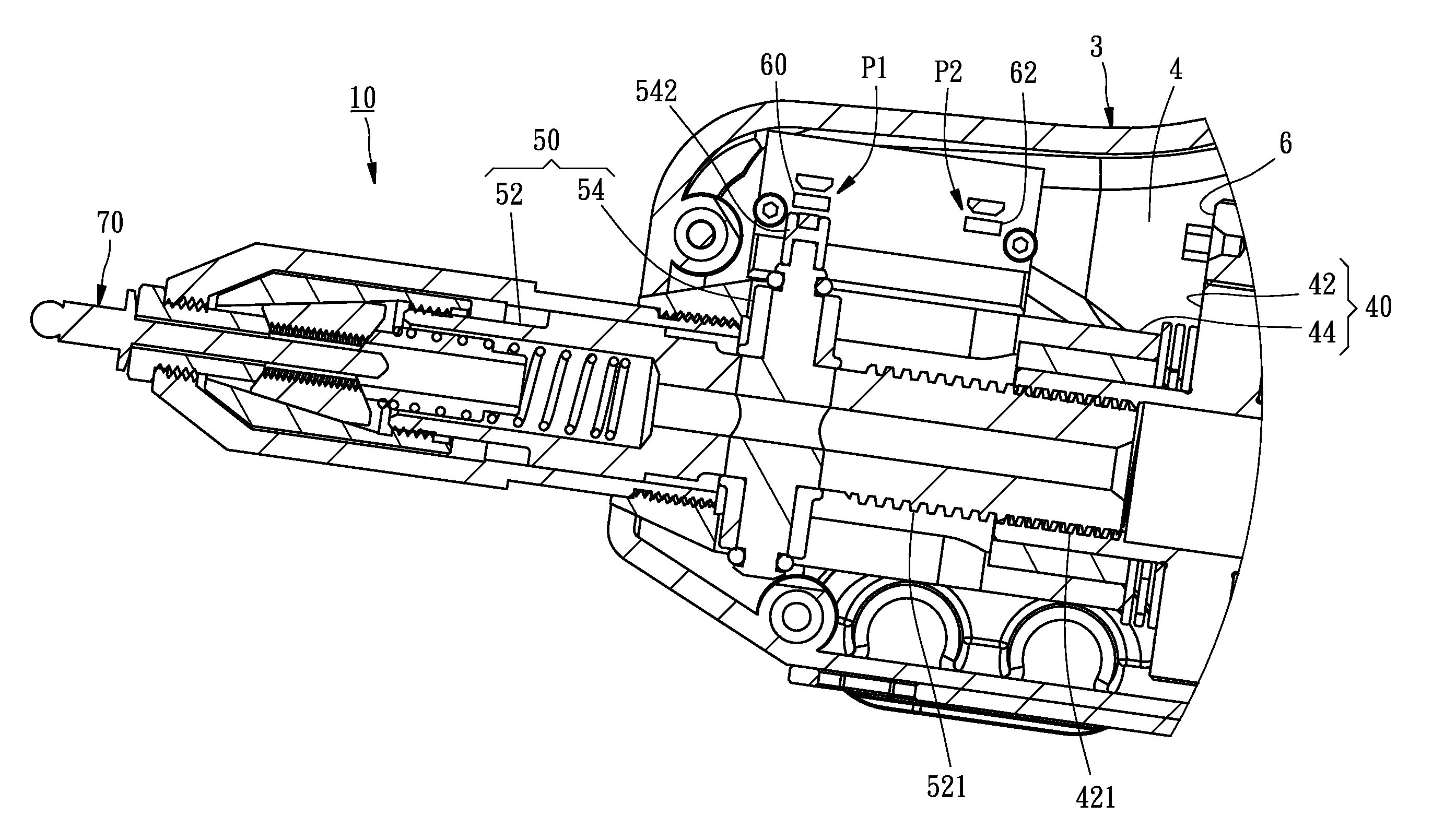
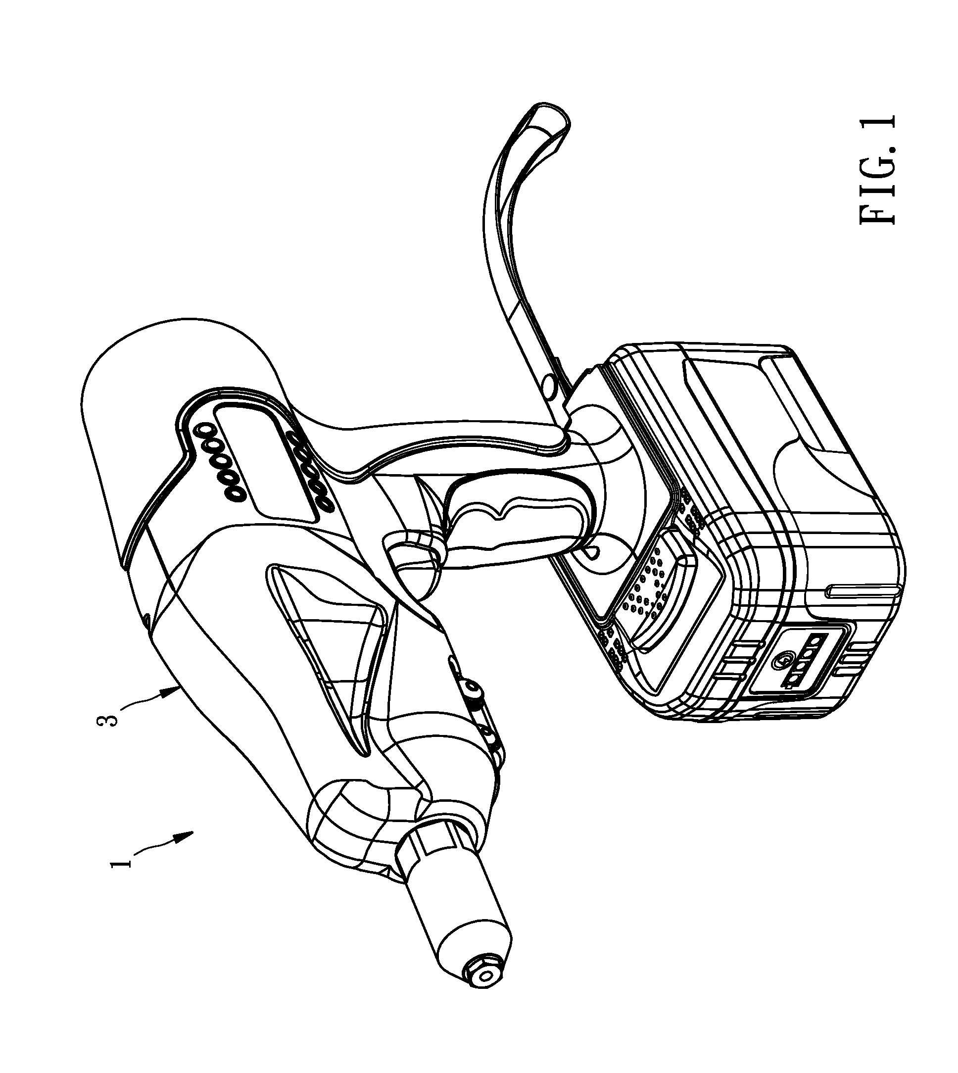
[0017]As shown in FIG. 1, a riveting unit 10 in accordance with a preferred embodiment of the present invention is installed in an electric rivet gun 1. Referring to FIGS. 1-3, the electric rivet gun 1 comprises a housing 3 having a chamber 4 therein, and a driving unit 5 installed in the camber 4 of the housing 3 and having a transmission shaft 6 with a first teeth portion 7. The riveting unit 10 comprises a transmission unit 40, a clamping jaw 50, a first sensor 60, and a second sensor 62.

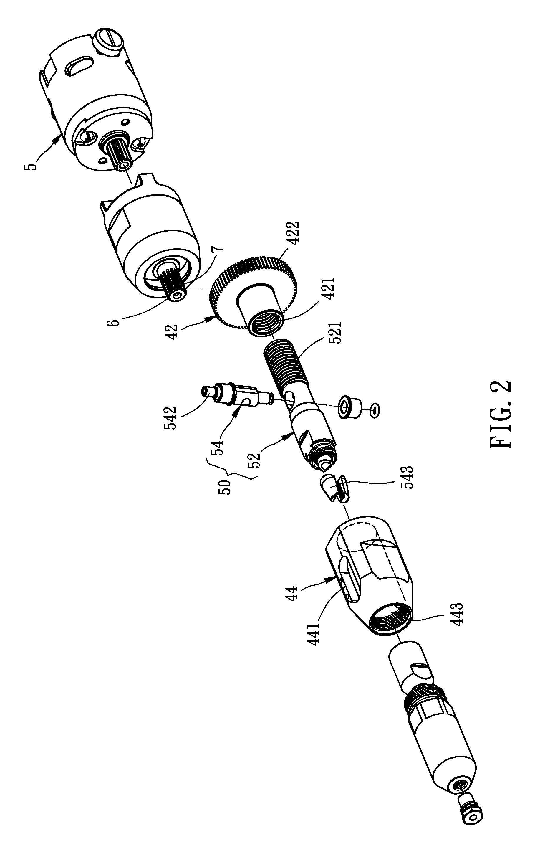
[0018]As shown in FIGS. 2-3, the transmission unit 40 is disposed in the chamber 4 of the housing 3, and provided with a wheel 42 and a restricting member 44. The wheel 42 has a first threaded portion 421 at a middle thereof and a second teeth portion 422 engaged with the first teeth portion 7 of the driving unit 5 such that the wheel 42 can be driven to rotate by the forward and backward rotation of the driving unit 5. The restricting member 44 has a through hole 443 sleeved on the first threade...


PUM

PropertyMeasurementUnit
axial movementaaaaaaaaaa
magnetic forceaaaaaaaaaa

Abstract

A riveting unit is assembled with an electric rivet gun, including a transmission unit, a clamping jaw having a locating portion driven by the transmission unit to be moveable between a first position and a second position, a first sensor detecting whether the locating portion of the clamping jaw is located at the first position, and a second sensor detecting whether the locating portion of the clamping jaw is located at the second position. When the locating portion of the clamping jaw is located at the first position, a blind rivet can be installed in the clamping jaw, and when the locating portion of the clamping jaw is located at the second position, the blind rivet can be ejected, and meanwhile the second sensor can allow the transmission unit to stop the movement of the clamping jaw, thereby preventing the clamping jaw from moving backwards excessively.

Description

BACKGROUND OF THE INVENTION[0001]1. Field of the Invention[0002]The present invention relates generally to an electric rivet gun, and more specifically to a riveting unit for an electric rivet gun that can prevent excessive backward movement of a clamping jaw for ensuring the normal operation of the electric rivet gun.[0003]2. Description of the Related Art[0004]A conventional electric riveter comprises a housing, a driving unit mounted in the housing, and a riveting unit having a transmission unit connected to the driving unit and a clamping jaw connected to the transmission unit. The clamping jaw can be driven to move forwards and backwards through the forward and backward rotation of the driving unit caused by a trigger, thereby attaining the purpose of ejecting a blind rivet.[0005]However, the operation time of the driving unit is decided by holding the trigger, that is to say, if a user presses the trigger too short, the blind rivet can't be ejected, and if the user presses the...

Claims


Application Information

Patent Timeline
Patent Type & Authority Applications(United States)
IPC IPC(8): B23P11/00
CPCB21J15/043B21J15/105B21J15/26Y10T29/53748Y10T29/5373Y10T29/49764Y10T29/53739B21J15/285
Inventor CHEN, HSIN-CHI
Owner TRANMAX MACHINERY
Why Eureka
Try Eureka