Actuator

Active Publication Date: 2010-06-10
NIPPON THOMPSON
View PDF5 Cites 32 Cited by
  • Summary
  • Abstract
  • Description
  • Claims
  • Application Information

AI Technical Summary

Benefits of technology

[0007]The present invention, therefore, has as its principal object to overcome the problems stated earlier and, in particular, to provide an actuator adapted for the use in a variety of machinery including assembling machines, measurement instruments, semiconductor manufacturing equipments, and so on. The present invention relates to an actuator adapted for the use in a variety of machinery including assembling machines, measurement instruments, semiconductor manufacturing equipments, and so on. The major concept of the present invention is to provide the actuator that has a frame to be fastened to base including a machine bed and so on, and a slider to move and guide unidirectionally relatively to the base any object mounted thereon. Another concept of the present invention is to provide an actuator weighing less, compact in construction, inexpensive in production, and helping get the overall machine slimmer than ever.
[0016]With the actuator constructed as stated earlier, the first and second rail members are firmly secured to the frame and the slider body, respectively, which are both made of the extruded shape of light-metal alloy. Especially, the constructional features of the present invention reside in contrivances to easily and simply fasten the first rail member to the frame and make it easier to install the upper sealing member between the frame and the slider body, closing up tightly the race between the raceway grooves.
[0018]In contrast, the second recess in the slider is made in a just rectangular shape in transverse section. This makes it easier to cut the second recess in the slider, even if small in size, in the correct location with accuracy and further to install properly the second rail member to the slider.

Problems solved by technology

The prior actuator as recited earlier, nevertheless, is generally bulky in construction.

Method used


Image

  • Actuator
  • Actuator
  • Actuator

Examples


Embodiment Construction

[0026]The actuator of the present invention will be well used in a diversity of machinery including assembling apparatus, testing / measuring instruments, processing machines, industrial robots, semiconductor manufacturing equipments, and so on.

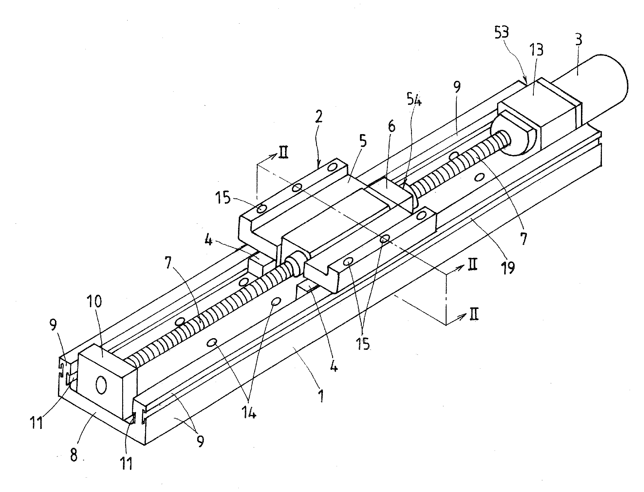
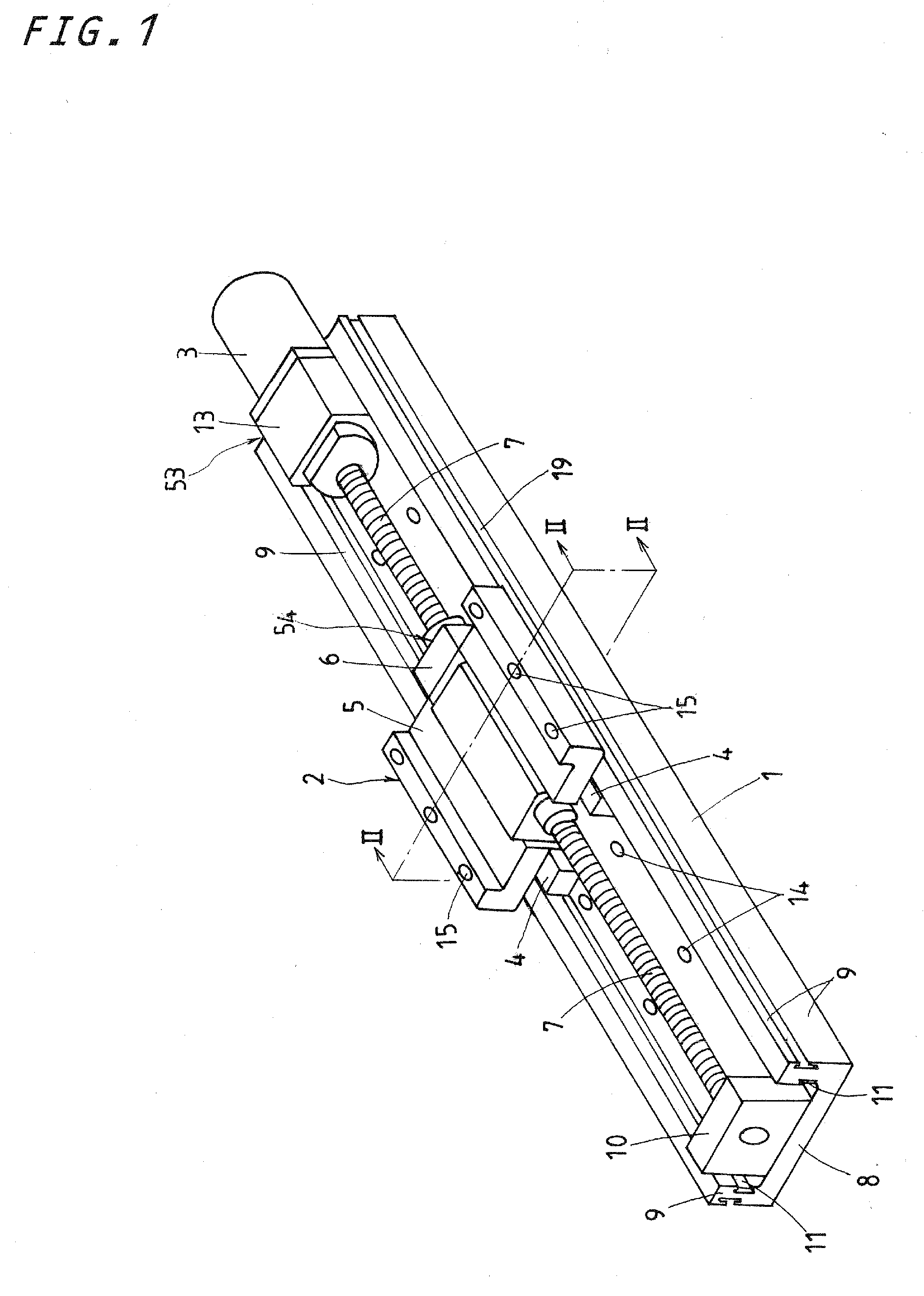
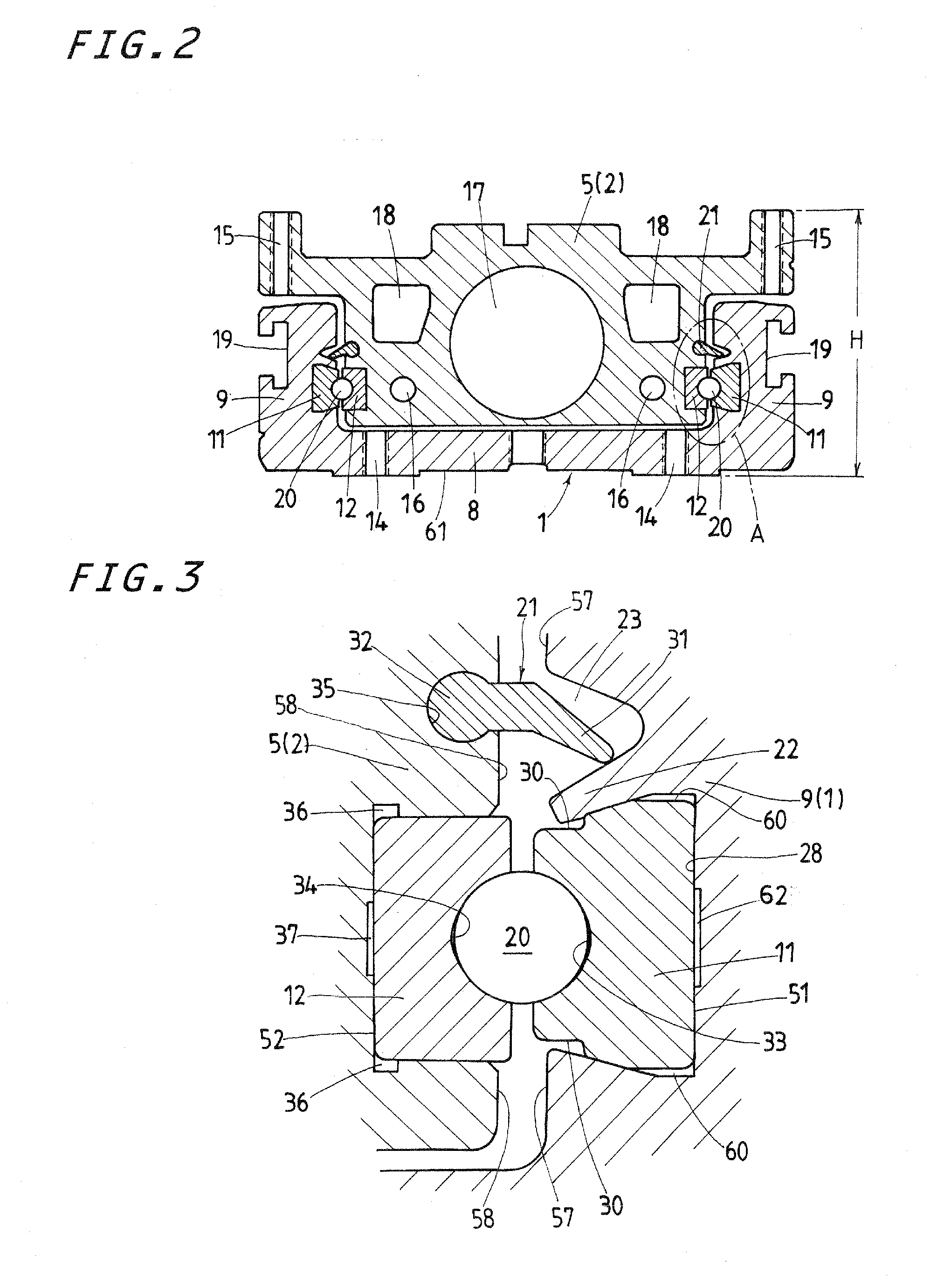
[0027]Referring now in detail to the accompanying drawings, a preferred embodiment of an actuator according to the present invention will be explained below. The actuator of the present invention, as shown in FIGS. 1 and 2, is mainly composed of an elongated frame 1, a slider 2 movable in one direction lengthwise of the frame 1 and a driving unit 53 having a motor 3 to energize the slider 2. The driving unit 53 is comprised of a ball-screw set 54 having a lead screw 7 held for rotation at opposite ends thereof with an end support 10 and a motor support 13 through bearings, not shown, and a lead nut 6 mating with the lead screw 7 and having mounted the slider 2 thereon, and the motor 3 to drive the lead screw 7. The frame 1 has threaded holes 14...


PUM


Abstract

An actuator has a frame and a slider body which are both made of extruded shapes of light-metal alloy. A first rail member is fastened to the frame by means of a simple construction. An upper sealing member is placed between the frame and the slider body. With the actuator constructed as stated earlier, the frame is an elongated extrusion of U-shape in transverse section whose side walls have first recesses of dovetail configuration to fit over first rail members and flanges. A slider has therein the slider body having second recesses of rectangular shape to fit over second rail members. There is further provided a driving unit to force the slider with respect to the frame. The first rail members each have the wedged configuration including tapered contours and dents, while the second rail members each have the rectangular shape.

Description

FIELD OF THE INVENTION[0001]The present invention relates to an actuator adapted for the use in a variety of machinery including assembling machines, measurement instruments, semiconductor manufacturing equipments, and so on, the actuator having an elongated frame, a slider and a driving unit.BACKGROUND OF THE INVENTION[0002]Actuators adapted for the sliding means to move and guide linearly any object are recently availed in extensively increased fields. Modern actuators are needed to be less in weight and height in transverse section, and more compact in construction. The actuators of the sorts as stated earlier have been used in, for example assembling machines, measurement instruments, various machines, industrial robots, semiconductor manufacturing equipments, and so on.[0003]An example of the prior actuators is disclosed in, for example the Japanese Laid-Open Patent Application No. H08-126 247, which is composed of a base and a slider movable with respect to the base. With the ...

Claims


Application Information

Patent Timeline
IPC IPC(8): F16H25/20B23Q1/26F16H25/22
CPCF16C29/004F16C29/063F16C29/088Y10T74/18648F16H25/2204F16H2025/2034F16H25/20F16C33/60
Inventor MORI, JUNYASAKAI, TETSUYA
Owner NIPPON THOMPSON
Why Eureka
Try Eureka