Neutral draw-out automatic transfer switch assembly and associated method

a technology of automatic transfer switch and assembly, which is applied in the direction of switchgear with a retractable carriage, emergency power supply arrangement, contact mechanism, etc., can solve the problem of avoiding the danger of both power sources being coupled to the system load during maintenance operations, and the assembly of bypass switch may be accidentally left in a neutral configuration

Active Publication Date: 2010-06-10
EATON INTELLIGENT POWER LTD
View PDF12 Cites 22 Cited by
  • Summary
  • Abstract
  • Description
  • Claims
  • Application Information

AI Technical Summary

Problems solved by technology

That is, the system typically draws power from the primary power source, however, if that source becomes disabled for any period of time, the secondary source is used.
Thus, the bypass switch assembly cannot be easily removed and maintenance thereon typically requires the system load (e.g. the hospital) to be powered down.
There is, however, a danger of accidentally having both sources of power coupled to the system load during maintenance operations; this occurs when either the switch assembly being serviced is configured to be coupled to the alternate power source prior to reinsertion, or, when the bypass switch assembly is switched over to the alternate power source while the switch assembly is being serviced and that switch assembly is not reconfigured prior to insertion.
There is also a danger that an error may be made when configuring the closed transition automatic transfer switch assembly prior to removing the switch assembly to be serviced.
That is, the bypass switch assembly may be accidentally left in a neutral configuration when the switch assembly being serviced is being removed.
When this occurs, if the switch assembly being removed is the active switch assembly, there is a strong possibility that arcing will occur as the active switch assembly is disengaged from the power source.

Method used


Image

  • Neutral draw-out automatic transfer switch assembly and associated method
  • Neutral draw-out automatic transfer switch assembly and associated method
  • Neutral draw-out automatic transfer switch assembly and associated method

Examples


Embodiment Construction

[0017]As used herein, “coupled” means a link between two or more elements, whether direct or indirect, so long as a link occurs.

[0018]As used herein, “directly coupled” means that two elements are directly in contact with each other.

[0019]As used herein, “fixedly coupled” or “fixed” means that two components are coupled so as to move as one while maintaining a constant orientation relative to each other.

[0020]As used herein and with reference to electrical components, “engage” shall mean temporarily coupled and allowing for electrical communication.

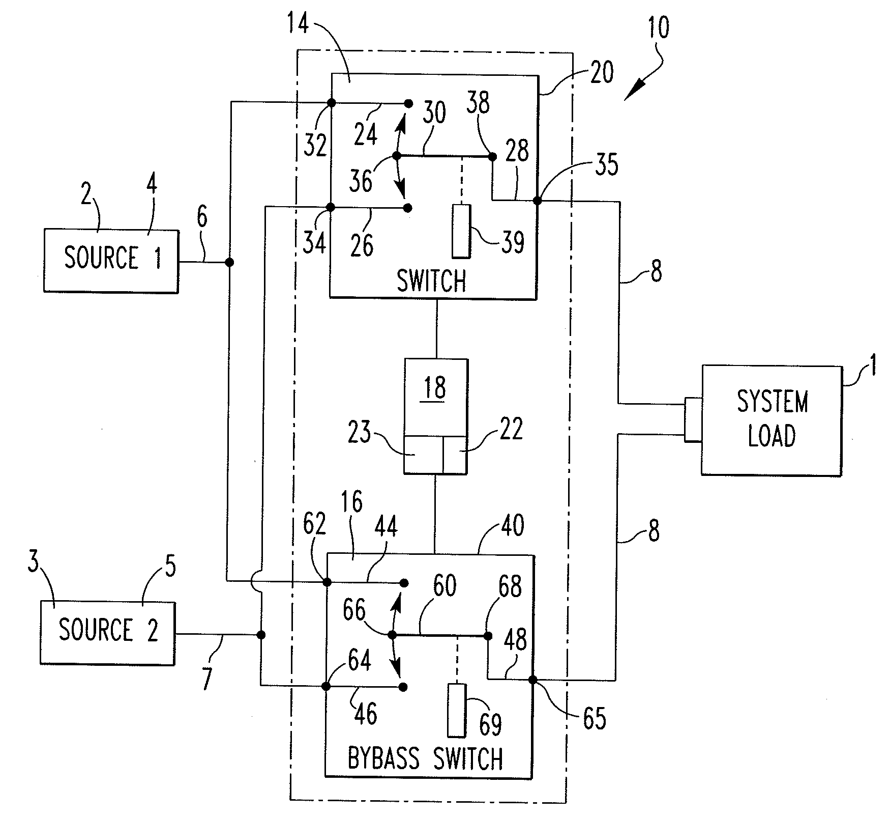
[0021]As used herein, a “power operated movable contact arm” is a contact arm structured to be moved by a motor or similar device. The motor may be remotely actuated, thus, the “power operated movable contact arm” may be remotely actuated.

[0022]As used herein, a “system load” is any load downstream of a transfer switch assembly but is, typically, a large installation such as, but not limited to, a building or manufacturing plant.

[0023]As ...


PUM


Abstract

An interlock assembly for a bypass isolation open or closed transition ATS assembly is disclosed. The interlock assembly ensures that a switch assembly being worked upon and / or being inserted is in a neutral configuration, i.e. the switch assembly is not engaging a power source. The interlock assembly is, preferably, an electrical interlock having a control system structured to configure the switch assemblies and to monitor the configuration of the switch assemblies. That is, the switch assemblies each include a power operated, conductive, movable contact arm. The position of each contact arm is controlled, and monitored by, the control system which controls the single actuator for each contact arm.

Description

BACKGROUND OF THE INVENTION[0001]1. Field of the Invention[0002]This invention relates to a bypass isolation open or closed transition automatic transfer switch assembly, commonly called an automatic transfer switch assembly (ATS assembly) and, more specifically, an ATS assembly structured to move into the neutral position prior to removal / insertion from / into an enclosure.[0003]2. Background Information[0004]Certain installations, e.g. hospitals, (hereinafter “the system load”) must have power systems structured to provide an uninterruptable power supply. The primary power source is typically the public power grid and the secondary power source is typically a generator. Both of these sources are structured to provide power over an extended period of time. That is, the system typically draws power from the primary power source, however, if that source becomes disabled for any period of time, the secondary source is used.[0005]An ATS assembly typically includes a first switch assembly...

Claims


Application Information

Patent Timeline
Patent Type & Authority Applications(United States)
IPC IPC(8): H01H9/26
CPCH01H3/161H02J9/06H01H2300/018H01H9/26H01H9/22
Inventor GIBBS, IRVING A.HOGLUND, JUSTINCLAUSEN, CATHLEENTOMASSI, MARK STEVENADAMS, JONATHAN SCOTT
Owner EATON INTELLIGENT POWER LTD
Why Eureka
Try Eureka