Electric motor

Inactive Publication Date: 2010-06-10
JOHNSON ELECTRIC INTERNATIONAL AG
View PDF3 Cites 31 Cited by
  • Summary
  • Abstract
  • Description
  • Claims
  • Application Information

AI Technical Summary

Benefits of technology

[0009]Accordingly, in one aspect thereof, the present invention provides an electric motor comprising: a stator and a rotor disposed in the stator, the stator comprising: a stator core having a yoke and a plurality of teeth extending inwardly from the yoke, a slot being formed between each pair of adjacent teeth; windings wound around the teeth; and a dielectric slot liner disposed between the

Problems solved by technology

Electric motors for low voltage use have relatively low slot insulation requirement and therefore a short creepage distance.
Electric motors designed for use with high voltage have a relatively high slot insulation requirement and therefore a large creepage distance.
This kind of slot insulation arrangement forms a short creepage dis

Method used


Image

  • Electric motor
  • Electric motor
  • Electric motor

Examples


Embodiment Construction

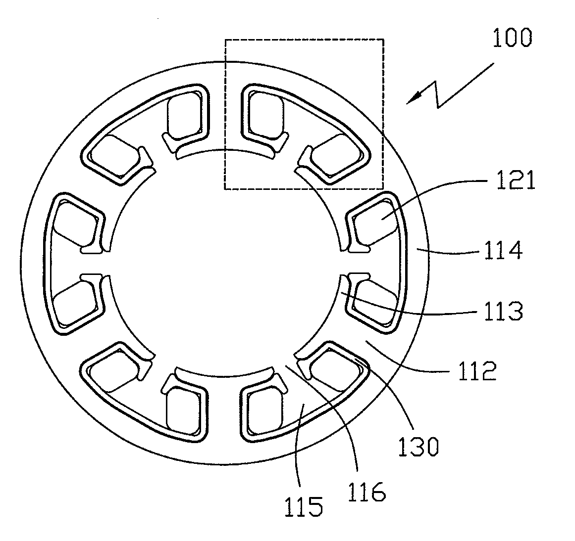
[0024]Referring to FIG. 4, a stator 100 of an electric motor in accordance with an embodiment of the present invention comprises a stator core and stator windings wound on the stator core. The stator core comprises a cylindrical yoke 114 and a plurality of teeth 112 extending inwardly from the yoke 114 in radial directions with even intervals in the circumferential direction. Each tooth 112 has a shoe 113 formed at a distal end thereof. A slot 115 is formed between each pair of adjacent teeth 112 and an opening 116 is formed between adjacent shoes 113 of the teeth 112 and communicates with the corresponding slot 115. Coils 121 forming the stator windings are wound on the teeth 112 and received in the slots 115. Prior to winding the coils 121, dielectric slot liners 130 are placed in each slot 115.

[0025]Referring to FIGS. 5-6, the slot liners 130 extend in the axial direction of the stator and the axial ends thereof extend beyond the corresponding axial end of the stator. Each slot l...


PUM


Abstract

An electric motor comprising a stator and a rotor, the stator comprising: a stator core having a yoke and a plurality of teeth extending inwardly from the yoke, a slot being formed between adjacent teeth; windings wound around the teeth; and a dielectric slot liner disposed between the stator core and the windings in each slot for insulating the stator core from the windings. Each slot liner comprises a body conforming the stator core in the slot and two ends each with a lip structure protruding relative to the body in a radial direction of the stator to increase the creepage distance between the winding and a distal end of a corresponding tooth of the stator core.

Description

CROSS REFERENCE TO RELATED APPLICATIONS[0001]This non-provisional patent application claims priority under 35 U.S.C. § 119(a) from Patent Application No. 200810218101.0 filed in The People's Republic of China on Dec. 5, 2008.FIELD OF THE INVENTION[0002]This invention relates to an electric motor and in particular, to an electric motor having slot liners.BACKGROUND OF THE INVENTION[0003]FIGS. 1 & 2 show a known three-phase brushless direct current (BLDC) motor having a stator and a rotor. The stator 12 of the motor comprises stator core 13, windings 20 and a dielectric frame 27. The stator core 13 comprises teeth 14 on which the windings 20 are wound. Slots 23 are formed between adjacent teeth 14. The rotor 16 of the motor comprises magnetic poles 18 formed by magnets attached at the surface of a rotor core 17. Each winding coil 22 wound on a corresponding tooth 14 has one terminal A, B or C and another terminal X, Y or Z connected to a common node 25. A dielectric slot liner 28 is i...

Claims


Application Information

Patent Timeline
IPC IPC(8): H02K3/34
CPCH02K3/345H02K3/325
Inventor CHU, JUN JIEYU, HUI FANG
Owner JOHNSON ELECTRIC INTERNATIONAL AG
Why Eureka
Try Eureka