
Semi-Automatic Relative Calibration Method for Master Slave Camera Control

Active Publication Date: 2010-06-10
HONEYWELL INT INC
View PDF23 Cites 83 Cited by
  • Summary
  • Abstract
  • Description
  • Claims
  • Application Information

AI Technical Summary

Benefits of technology

[0009]According to another aspect of the present disclosure, there is provided a security system that includes a first camera recording a first field of view and a second camera including a panning function, a tilting function, and a zooming (or magnifying) function recording a second field of view. The first camera records a target in the first field of view, and outputs a control signal to a computing device. The signal is indicative of a location parameter of the target in the fixed field of view.
[0010]The computing device receives the control signal and converts the control signal to a second signal. The second camera receiving the second signal engages in at least one f

Problems solved by technology

Additionally, these large field of view cameras are economically viable for such applications due to their cost.
However, these wide field of view cameras are often poor in their ability to provide adequate resolution for clearly identifying targets located within the field of view of the camera.
Generally, pan, tilt, zoom cameras are more expensive than the previously mentioned cameras.
Unfortunately, if used alone, a single pan, tilt, zoom camera cannot effectively monitor a large and wide field of view of the secured area.
This large number of PTZ cameras can also dramatically increase the costs associated with the system.
Generally, large field of view cameras, and pan, tilt, zoom cameras are generally difficult to coordinate and control together.
Secondly, images taken by one camera system are generally not immediately compatible with the images taken from a second camera system.
However, these procedures are time intensive and do not result in reliable calibration of the two systems, with all sets of images, and particularly are deficient when the target is fast moving through the field of view.

Method used


Image

  • Semi-Automatic Relative Calibration Method for Master Slave Camera Control
  • Semi-Automatic Relative Calibration Method for Master Slave Camera Control
  • Semi-Automatic Relative Calibration Method for Master Slave Camera Control

Examples


Embodiment Construction

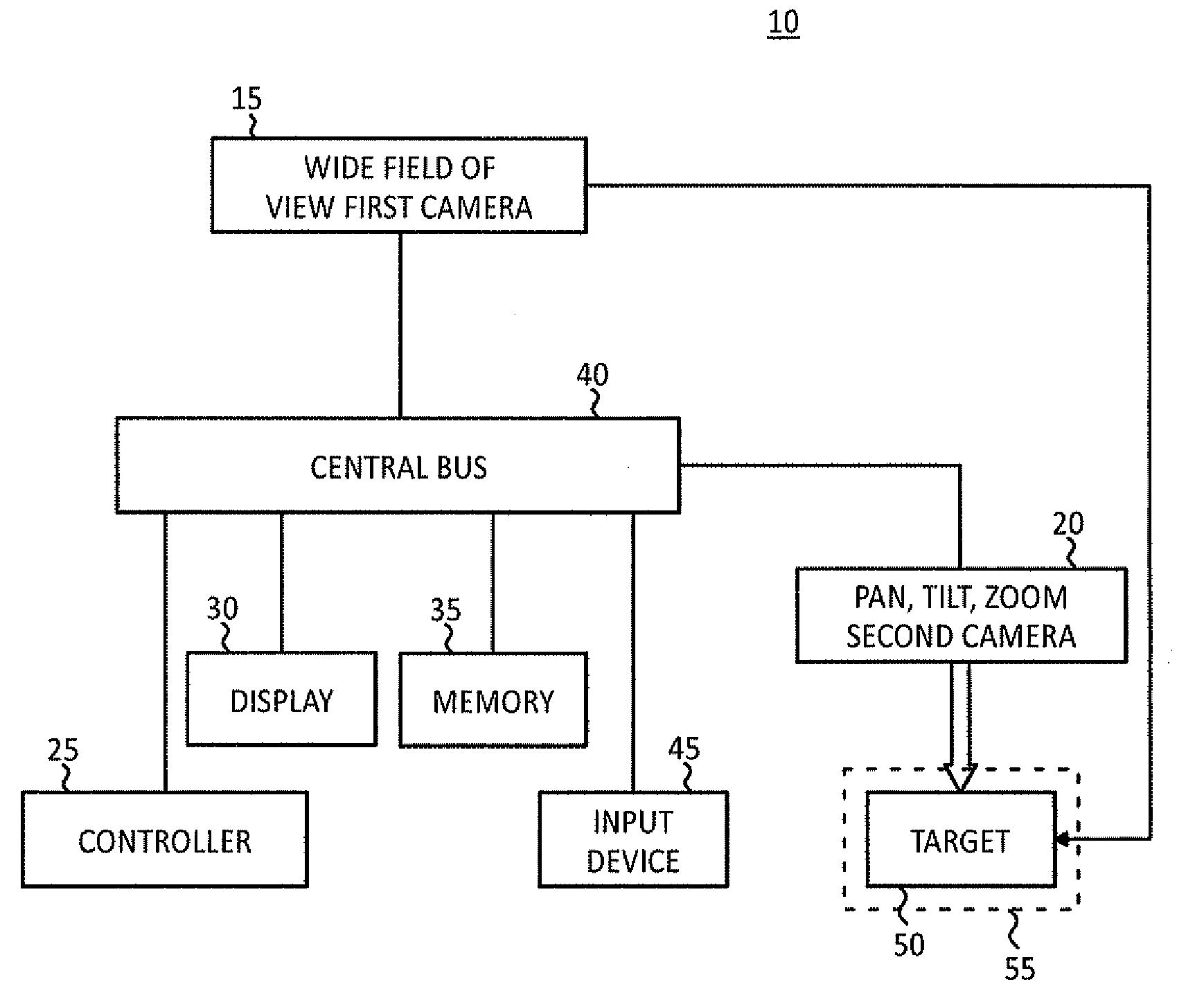
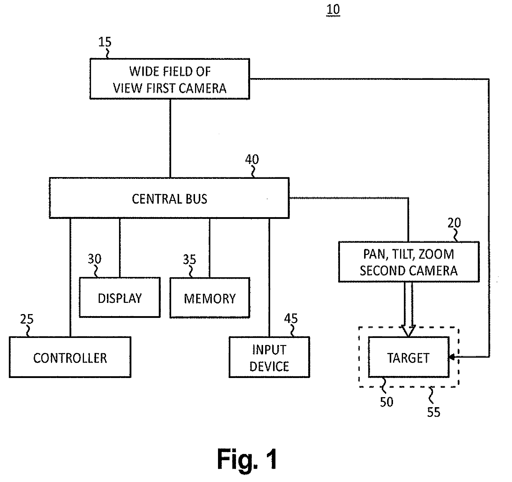
[0020]The present disclosure is directed to a security system 10 that includes a first camera 15 and a second camera 20 that cooperate with one another in a master-slave control relationship. In the exemplary embodiment, each of the first camera 15 and the second camera 20 are operatively connected to a controller 25 by suitable connectors and provide video signals, which are converted to a digital format and supplied to the controller 25. The controller 25 outputs the video signals to a display system 30 where a security guard or similar individual can monitor the images on the display system 30 representative of the images being recorded or captured from the first and the second cameras 15 and 20. In the exemplary embodiment, the controller 25 is operatively connected to a memory 35 by a central bus 40.

[0021]In the exemplary embodiment, the security system 10 provides for a master-slave control relationship between the first camera 15 and the second camera 20 so at least one camer...


PUM


Abstract

A method for capturing surveillance images includes of a secured area has a first camera with a first field of view and a second camera with a second field of view. An optical center is determined for the second field of view. A magnification ratio is determined between a target located in the first field of view relative to the second field of view. A pan and tilt model is determined that provides a relationship between a first camera coordinates and pan and tilt values to position the second camera at the optical center. A target is captured in the first field of view and the second camera is controlled to record the target in the second field of view with the second field of view being an enhanced view relative to the first field of view.

Description

FIELD OF THE INVENTION[0001]This invention generally relates to security systems. More particularly, the present disclosure relates to a surveillance system with a first wide field of view camera acting together with a second pan, tilt, zoom camera in a master-slave control relationship. The first wide field of view camera can monitor an area for a target of interest. The second pan, tilt, zoom camera, once properly calibrated, can automatically obtain an enhanced view of the target with the help of the first camera.BACKGROUND OF THE INVENTION[0002]Security systems are known in the art. Often a security guard will monitor an area for a target of interest, such as, for example a person, or automobile in a secure area. Generally, to capture a large area, one would record the secure area using a camera having a large field of view. Additionally, these large field of view cameras are economically viable for such applications due to their cost. However, these wide field of view cameras a...

Claims


Application Information

Patent Timeline
IPC IPC(8): H04N7/18
CPCH04N7/181G08B13/19643
Inventor MOHANTY, KAMINI KANTAGELLABOINA, MAHESH KUMARWILSON, JEREMY CRAIG
Owner HONEYWELL INT INC
Features
  • Generate Ideas
  • Intellectual Property
  • Life Sciences
  • Materials
  • Tech Scout
  • Unparalleled Data Quality
  • Higher Quality Content
  • 60% Fewer Hallucinations
Learn More