
System for Tailoring a Transfer NIP Electric Field for Enhanced Toner Transfer in Diverse Environments

Active Publication Date: 2010-06-10
LEXMARK INT INC
View PDF17 Cites 7 Cited by
  • Summary
  • Abstract
  • Description
  • Claims
  • Application Information

AI Technical Summary

Benefits of technology

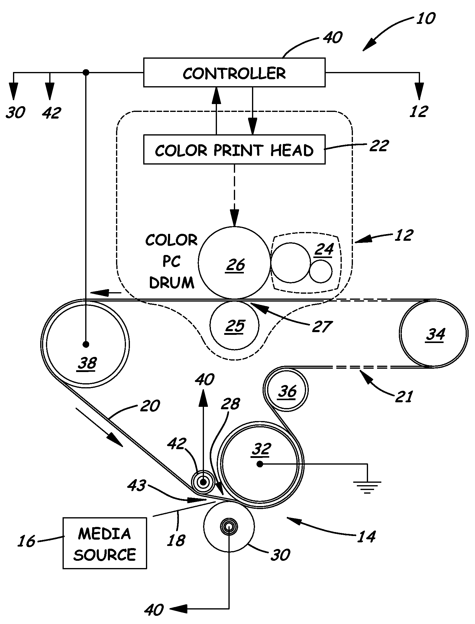
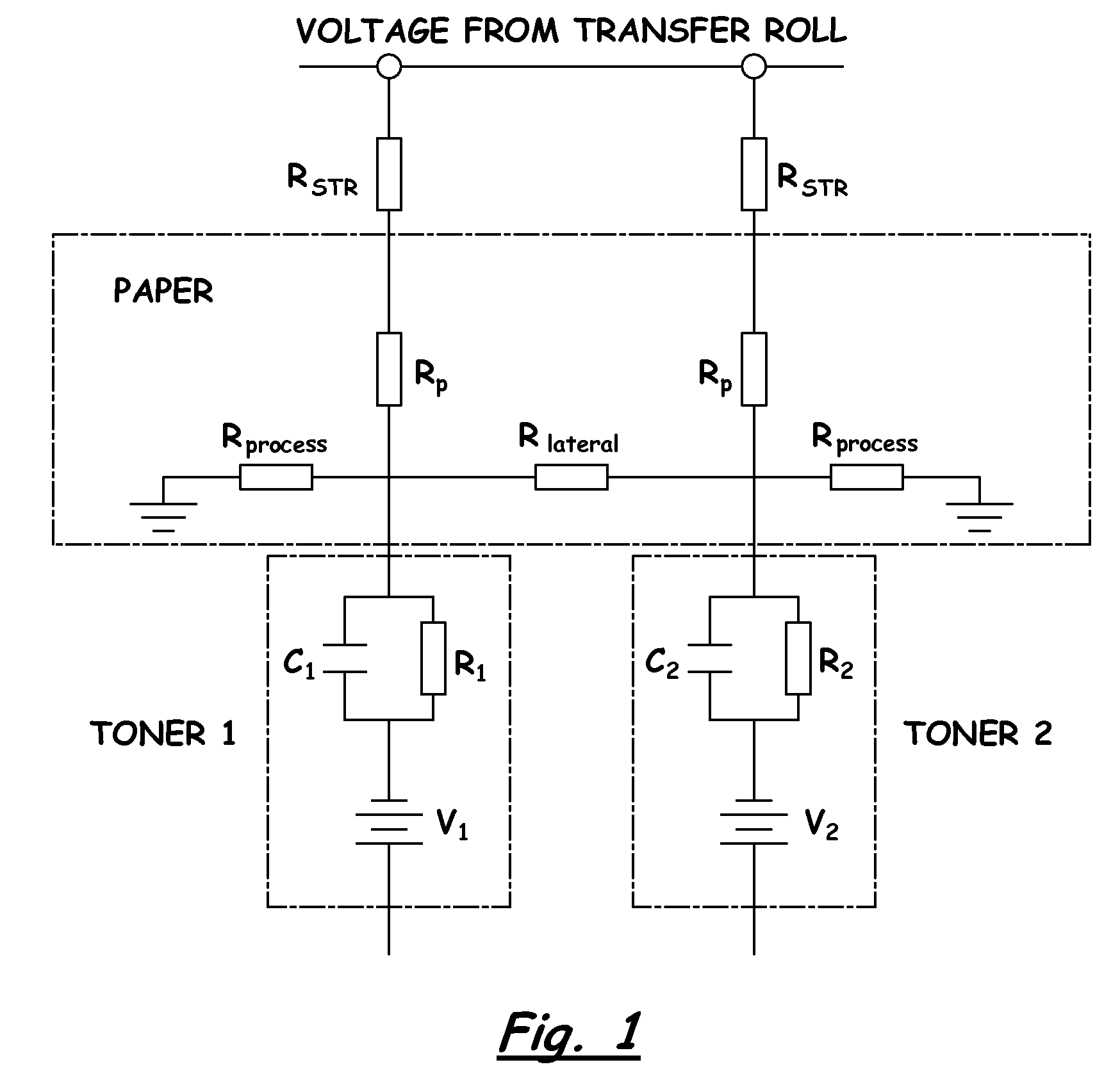
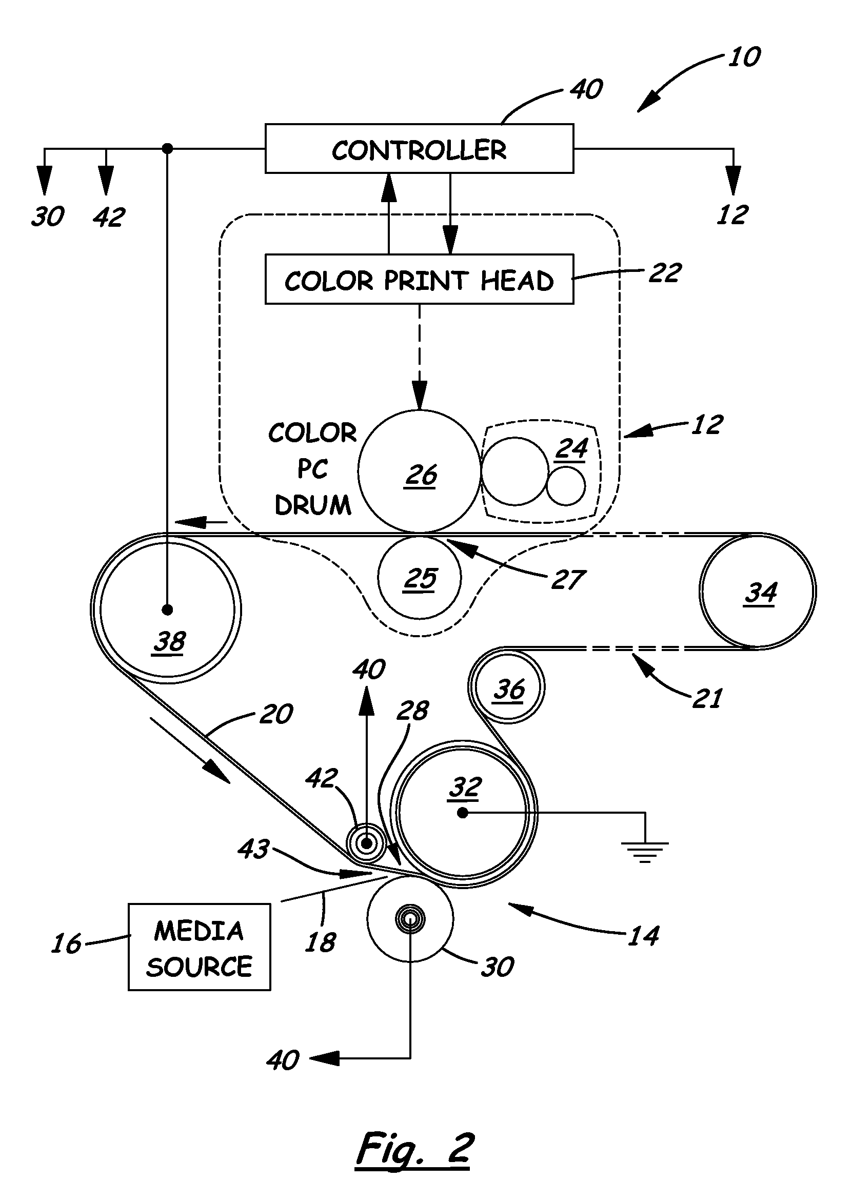
[0016]The present invention meets this need by providing an innovation that enables a charge field to be tailored to meet the needs of the diverse environments. Previous efforts have attempted to achieve a similar goal by using complex mechanical devices that are too expensive and unreliable to be commercially viable. The innovation of the present invention is elegant in its simplicity and its effectiveness. The innovation involves incorporation of a pre-nip roll touching a low surface resistivity transfer belt biased to reduce field strength entering a transfer nip. The field strength can be increased by placing the pre-nip roll at zero potential as compared to the backup roll. Also, isolating conductive paper from grounding paths improves performance in diverse environments of temperature and humidity.
[0018]In another aspect of the present invention, a system for tailoring a second transfer nip electric field for enhanced toner transfer in diverse environments includes a plurality of image-forming first transfer stations, a second transfer station having a second transfer nip, and an endless transfer belt transported in an endless path passing, first, through a plurality of first transfer nips at the first transfer stations where toner forming an image is deposited on the transfer belt and, second, into and through the second transfer nip of the second transfer station where the toner is transferred from the transfer belt onto a media sheet. The second transfer station includes a rotatable transfer roll having a first potential, a rotatable backup roll having a second potential and forming the second transfer nip between the rolls as the rolls counter-rotate relative to one another, and a rotatable pre-nip roll having a third potential and being positioned upstream from the transfer and backup rolls and the transfer nip such that the transfer belt moves past the pre-nip, transfer and backup rolls and separately makes contact with, wraps partially around, and rotates each of the pre-nip, transfer and backup rolls as a media sheet is fed into the transfer nip after first passing through a gap defined between the pre-nip roll and the transfer roll such that by presetting the position, geometry and potential of the pre-nip roll relative to the transfer and backup rolls an electric field at the second transfer nip can be tailored for enhanced toner transfer from the transfer belt to the media sheet in diverse environments.

Problems solved by technology

Previous efforts have attempted to achieve a similar goal by using complex mechanical devices that are too expensive and unreliable to be commercially viable.

Method used


Image

  • System for Tailoring a Transfer NIP Electric Field for Enhanced Toner Transfer in Diverse Environments
  • System for Tailoring a Transfer NIP Electric Field for Enhanced Toner Transfer in Diverse Environments
  • System for Tailoring a Transfer NIP Electric Field for Enhanced Toner Transfer in Diverse Environments

Examples


Embodiment Construction

[0025]The present invention now will be described more fully hereinafter with reference to the accompanying drawings, in which some, but not all embodiments of the invention are shown. Indeed, the invention may be embodied in many different forms and should not be construed as limited to the embodiments set forth herein; rather, these embodiments are provided so that this disclosure will satisfy applicable legal requirements. Like numerals refer to like elements throughout the views.

[0026]Referring now to FIG. 2, the color EP imaging machine 10 to which is applied the system of the present invention is a two transfer system. The imaging machine 10 includes, in part, a plurality of first transfer, color image forming, stations 12 (only one being shown), a second transfer station 14, a media source 16 for feeding one at a time a media sheet 18, of paper for instance, to the second transfer station 14, and an intermediate transfer belt 20 arranged to be moved along an endless path 21 w...


PUM


Abstract

A system for tailoring a transfer nip electric field includes a transfer roll, a backup roll forming a transfer nip with the transfer roll, and a pre-nip roll positioned upstream from the transfer and backup rolls and the transfer nip such that a toner image-supporting transfer belt moving past the pre-nip, transfer and backup rolls separately makes contact with, wraps partially around, and rotates each of the rolls as a media sheet is fed into the transfer nip after first passing through a gap defined between the pre-nip and transfer rolls such that by presetting the position, geometry and charge of the pre-nip roll relative to the transfer and backup rolls and the transfer belt an electrical field at the transfer nip can be tailored for enhanced toner transfer from the transfer belt to the media sheet.

Description

CROSS REFERENCES TO RELATED APPLICATIONS[0001]None.BACKGROUND[0002]1. Field of the Invention[0003]The present invention relates generally to electrophotographic (EP) imaging machines and, more particularly, to a system for tailoring a transfer nip electric field for enhanced toner transfer in diverse environments.[0004]2. Description of the Related Art[0005]Color EP imaging machines, such as color laser printers, typically utilize an intermediate transfer belt to accumulate a final output image from a plurality of individual images, known as separations or layers. The layers are placed onto the intermediate transfer belt in succession as the belt passes by a photoconductive (PC) drum associated with each of the different color, first transfer, stations. Once the intermediate transfer belt has traversed all of the PC drums the resulting, or final, output image will be transferred to a print medium, for instance a sheet of paper, at a second transfer station. The system of this color ...

Claims


Application Information

Patent Timeline
IPC IPC(8): G03G15/16G03G15/00
CPCG03G15/1605G03G15/0131
Inventor GIBSON, NICHOLAS FENLEYKEMP, BRANDON ALDENMATTINGLY, BRAD EDWARDPHILLIPS, MICHAEL TODDPICKETT, PETER BROWNREAM, GREGORY LAWRENCESMITH, CHRISTOPHER MICHAELWHITNEY, JULIE ANN GORDON
Owner LEXMARK INT INC
Learn More