
Printing device

Inactive Publication Date: 2006-11-16
SCHOTT AG
View PDF9 Cites 0 Cited by
  • Summary
  • Abstract
  • Description
  • Claims
  • Application Information

AI Technical Summary

Benefits of technology

[0006] It is one object of this invention to provide a printing device of the type mentioned above but with an improved toner transfer from the transfer medium to the substrate. Also, when used in a multi-color printing installation, the printing device is also intended to avoid the known problems, in particular because of the excessive heat introduction.

Problems solved by technology

With such an arrangement, the area to be heated is substantially limited to the substrate, so that heating of the printing unit, or the introduction of heat, beyond this is limited.

Method used


Image

  • Printing device
  • Printing device
  • Printing device

Examples


Embodiment Construction

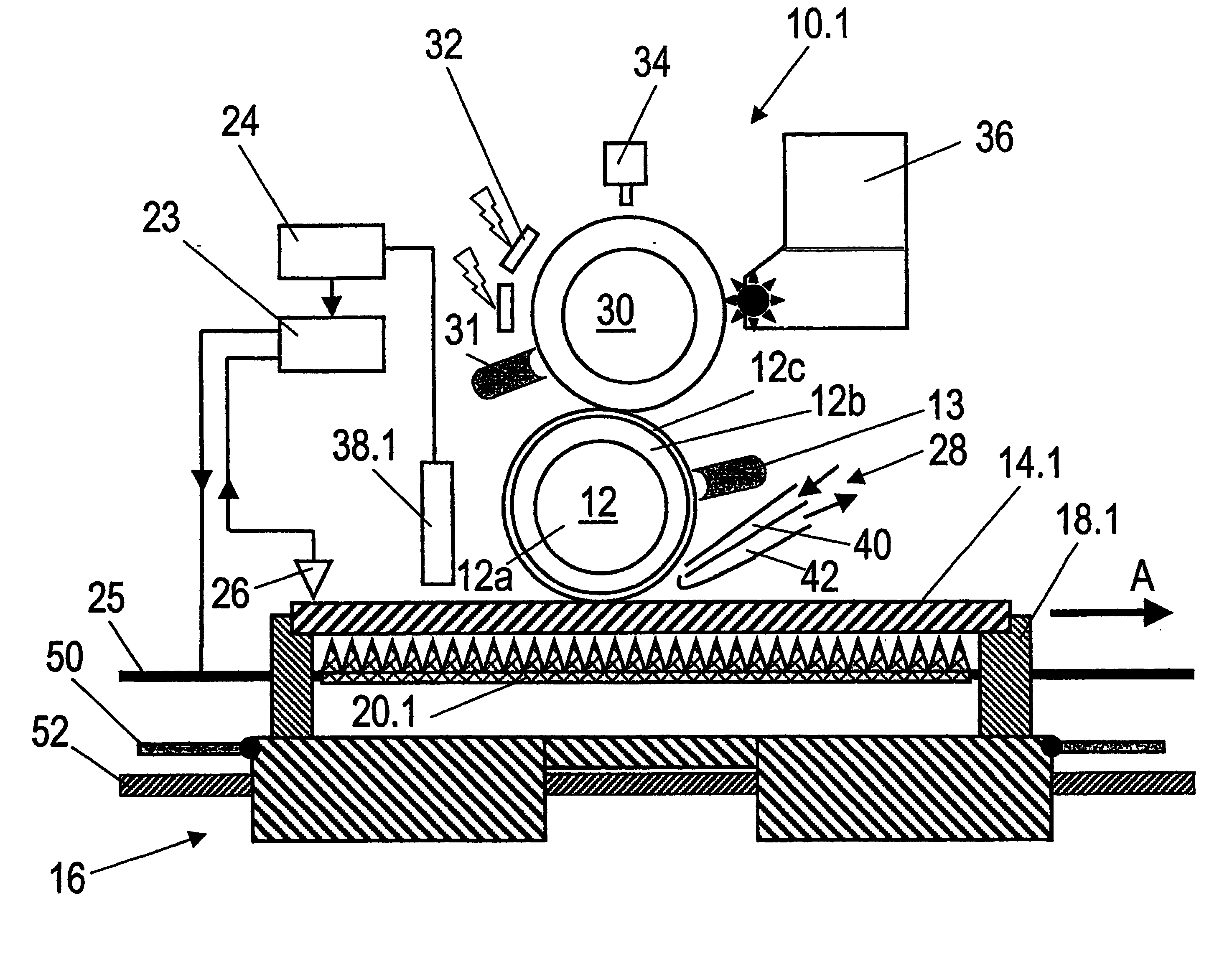
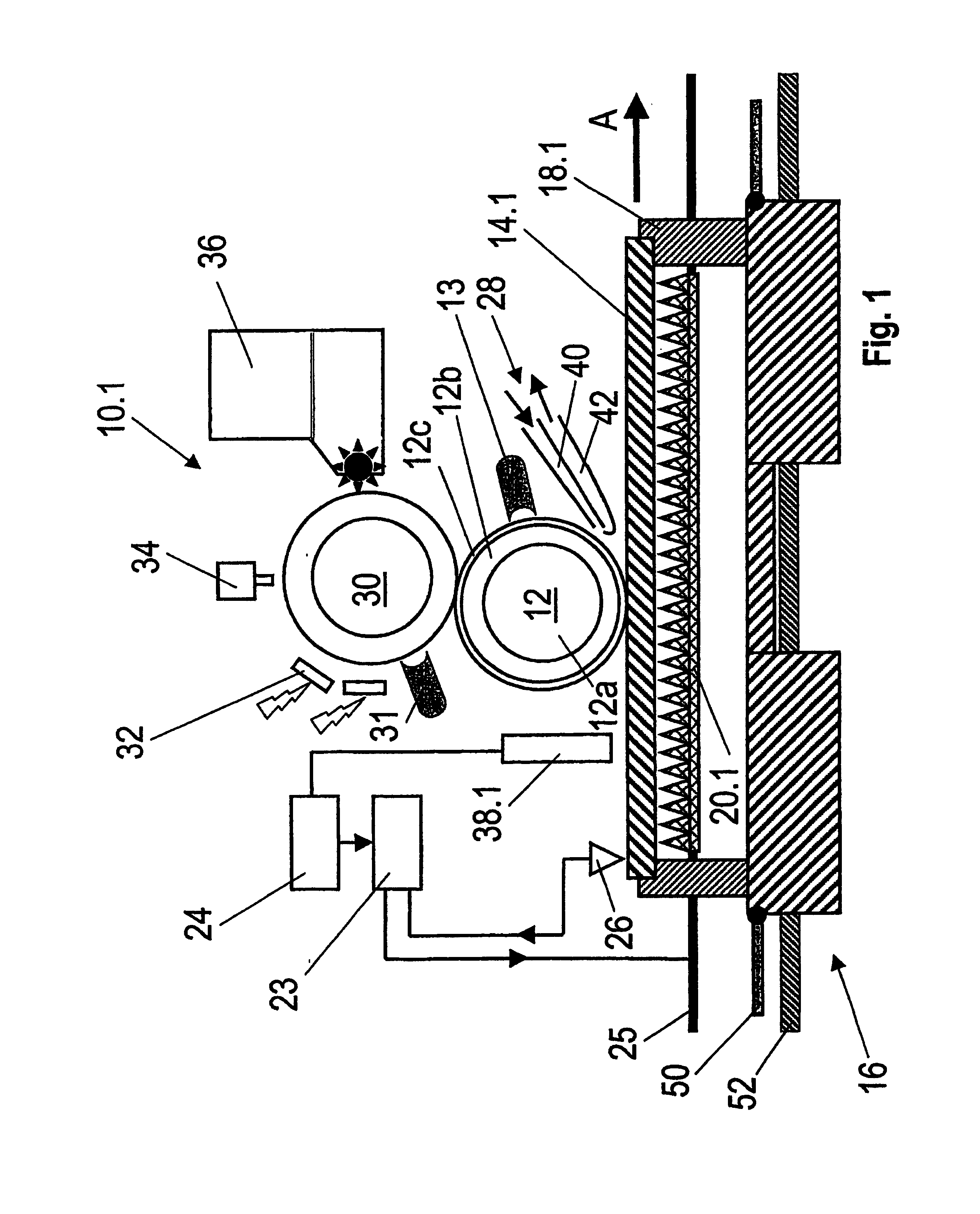
[0039] A printing device with an electro-graphic printing unit 10.1 is shown in FIG. 1. It has a roller-shaped photo-conductor 30 and has a uniform charge on its surface, by a charging corona 32. This charge is partially removed, corresponding to the pattern to be printed, by an adjoining LED-writing head or a laser arrangement 34, so that a lateral charge image is created. A developer unit 36 applies toner powder to the discharged areas of the photo-conductor surface. The toner image thus developed is transferred in a transfer zone to a transfer medium 12. The transfer medium 12 has a base roller body 12a. A resilient, electrically semi-conducting intermediate layer 12b is applied to the base roller body 12a. It can comprise, for example, silicon, EPDM or polyurethane. An anti-adhesion coating 12c is arranged indirectly or directly above the intermediate layer 12b and forms the roller surface.

[0040] A cleaning unit 31 is arranged at the photo-conductor 30, and a cleaning unit 13 a...


PUM


Abstract

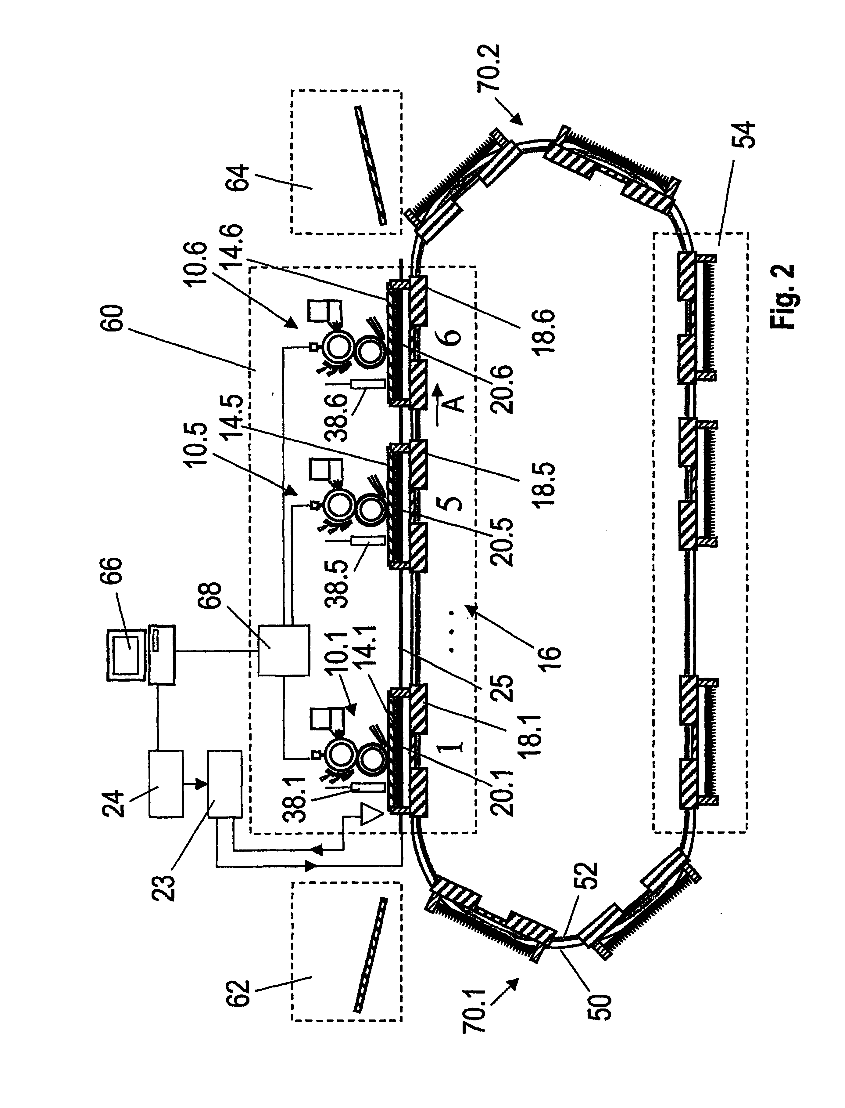
A printing device, including at least one electrophotographic printing unit with a transfer medium for the transfer of a toner powder to a substrate in a transfer zone. One or several substrates may be run through the transfer zone by a transport system. The transport system includes a heated housing device for each substrate, having one or several heating elements for the introduction of heat energy into the substrate. A cooling device is provided for the transfer medium of each printing unit, which extracts heat energy from the transfer medium. There can be a number of serially arranged printing units, for the printing of each substrate, each with a different color.

Description

BACKGROUND OF THE INVENTION [0001] 1. Field of the Invention [0002] This invention relates to a printing device, having at least one electro-photographic printing unit, to which a transfer medium for transferring a toner powder to respectively one substrate in a transfer zone is assigned, wherein one or several substrates can be conducted through the transfer zone by a transport system. [0003] 2. Discussion of Related Art [0004] A printing device is known from U.S. Pat. No. 5,988,068. A revolving endless belt is assigned as the transfer medium to an electro-photographic printing unit. A photo-conductor rolls off the latter for transferring an image having toner powder. The toner image can be applied to a substrate. Thus, the substrate is conducted past the transfer medium by a transport system. In this case the transfer medium rolls off the substrate surface to be imprinted. According to U.S. Pat. No. 5,988,068, there are two heating elements for improving the toner transfer. The fi...

Claims


Application Information

Patent Timeline
IPC IPC(8): G03G15/00G03G15/16
CPCG03G2215/1671G03G15/1665
Inventor SCHULTHEIS, BERNDJUNG, DIETERKOBRICH, HOLGER
Owner SCHOTT AG
Learn More