Endoscope with rotary drum and operating method

a technology of endoscope and rotating drum, which is applied in the field of endoscope with rotating drum, can solve the problems of limiting the installation space of imaging system or sensor electronics, restricting the functionality of imaging system or cross-section of work channel, etc., and achieves the effect of restricting the field of view or the resolution of imaging system and facilitating us

Pending Publication Date: 2022-06-09
KARL STORZ GMBH & CO KG
View PDF19 Cites 1 Cited by
  • Summary
  • Abstract
  • Description
  • Claims
  • Application Information

AI Technical Summary

Benefits of technology

[0010]The present invention is therefore based on the object of proposing an endoscope which facilitates the use of a large work channel in relation to the internal diameter of the shaft tube and which avoids the known problems from the prior art without restricting the field of view or the resolution of the imaging system in the process.

Problems solved by technology

Particularly in the case of simultaneous use of an optical imaging system and a work channel for instruments and / or channels for the fluid guidance, at least the functionality of the imaging system or the cross section of the work channel is restricted by the bounding and small external dimensions of a shaft tube of the endoscope.
As a result of the embodiment of the endoscope with a twice pivotable rotating drum it is possible to enlarge the field of view of the imaging system in particular, with however the control mechanism requiring the entire volume of the rigid shaft tube and hence not allowing a work channel to be arranged in the interior of the rigid shaft tube.
The installation space for the electronics of an imaging system or a sensor is restricted, especially in favor of using comparatively large work channels for fluid and / or instrument guidance, and so a small sensor with a low resolution is usually used for the imaging.

Method used


Image

  • Endoscope with rotary drum and operating method
  • Endoscope with rotary drum and operating method
  • Endoscope with rotary drum and operating method

Examples


Embodiment Construction

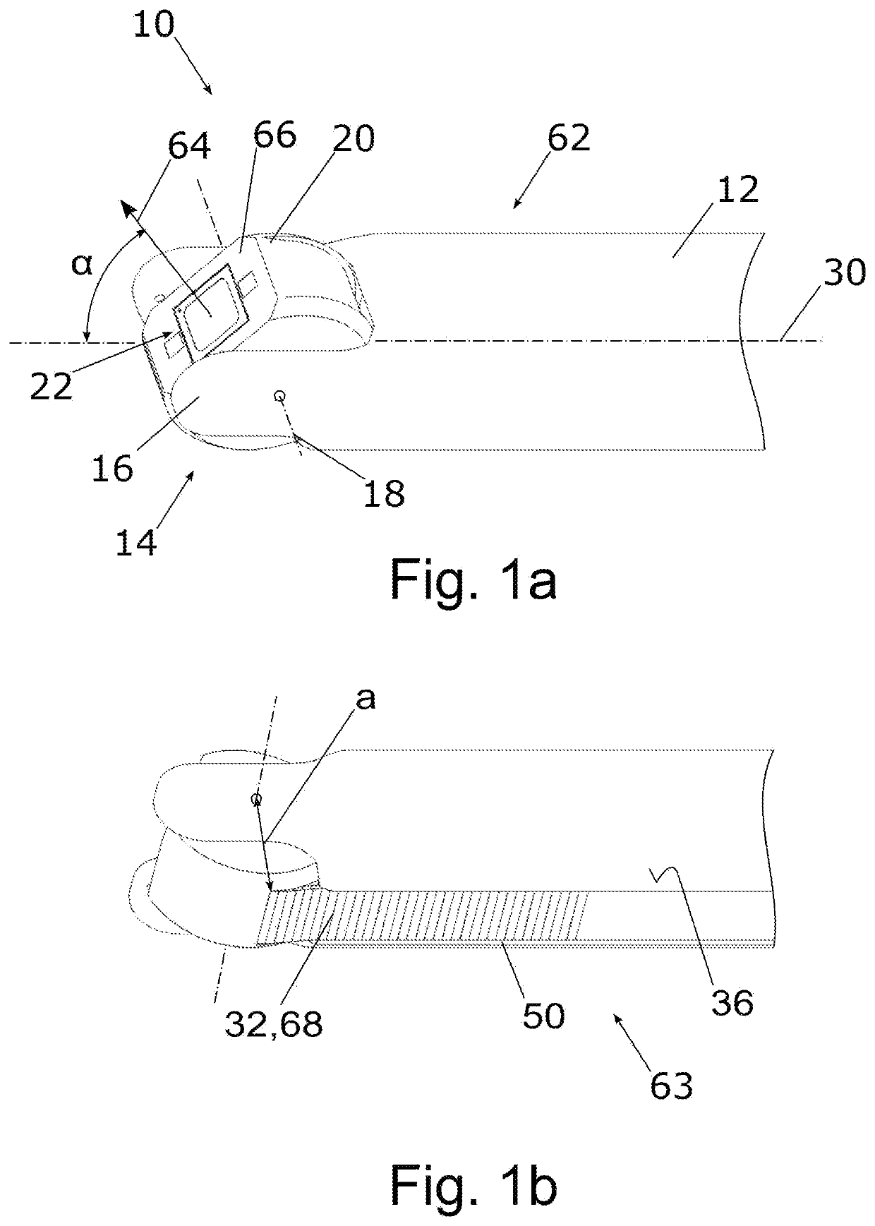
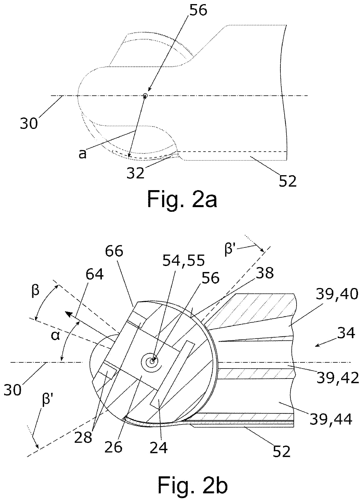
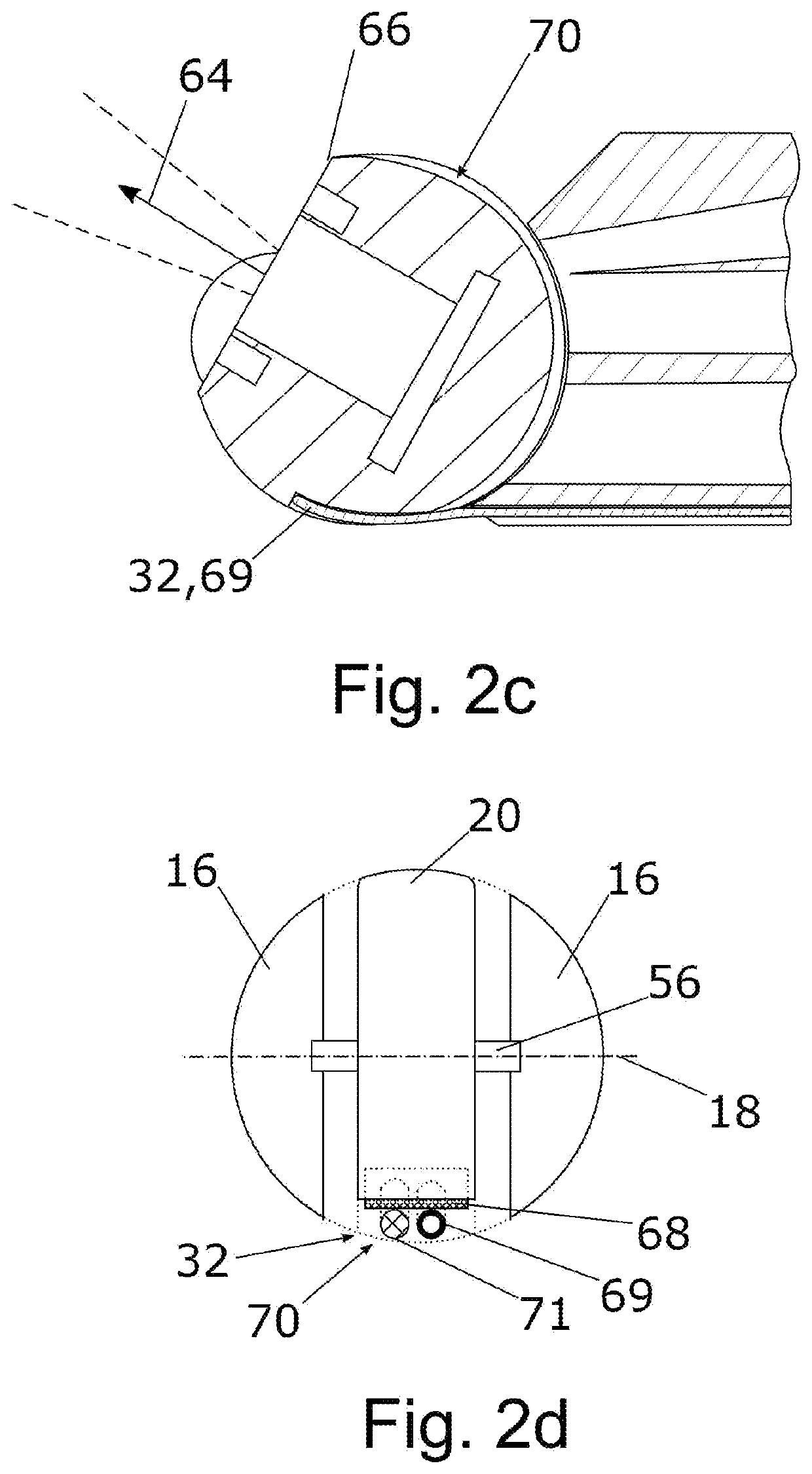
[0061]FIG. 1a illustrates an endoscope 10 with a rotating drum 20 on a distal end 14 of an elongate rigid shaft tube 12, wherein the rotating drum 20 is mounted at the distal end 14 of the shaft tube 12 by means of a bearing fork 16 so as to be rotatable about a first axis of rotation 18. An optical imaging system 22, which preferably comprises an electronic image recorder 24, an imaging optical unit 26 and an illumination device 28 as shown in detail in FIG. 2b, is arranged in the rotating drum 20. The rotating drum 20 is illustrated from an upper side 62 of the shaft tube 12, wherein a viewing direction 64 of the imaging system 22 is pivotable through an angle α with respect to the longitudinal axis 30 and the bearing fork 16 does not restrict the viewing direction 64 of the imaging optical unit 26. By pivoting the rotating drum 20, and hence the viewing direction 64, it is possible to cover an angle α of preferably more than 130° and an observation region β′ as per FIG. 2b. By ro...


PUM


Abstract

An endoscope with a rotating drum or a rotation module, in particular for use as a sterile disposable instrument, having an elongate rigid and/or flexible shaft tube which at a distal end mounts the rotating drum, so as to be rotatable about at least one first axis of rotation, an optical imaging system being arranged in the rotating drum, with the at least one first axis of rotation running approximately transversely to a longitudinal axis of the shaft tube and with the endoscope having at least one control line for rotating the rotating drum. Here, the at least one control line of the rotating drum runs on an outer side/outer face of the shaft tube, and is fastened to the rotating drum at at least one lever distance (a) from the at least one first axis of rotation.

Description

TECHNICAL FIELD[0001]The present invention relates to an endoscope with a rotating drum, in particular for use as a sterile disposable instrument, according to the preamble of claim 1 and to a method for operating the endoscope.BACKGROUND OF THE INVENTION[0002]Generic endoscopes are used as an observation instrument, in particular for medical operations, preferably for surgical operations, with said endoscopes being designed to have the smallest possible external dimensions for the purposes of a minimally invasive intervention. In addition to the use as an observation instrument, the endoscope can also be equipped with medical instruments and / or channels for fluid guidance, especially for laparoscopic, hysteroscopic or arthroscopic operations. Particularly in the case of simultaneous use of an optical imaging system and a work channel for instruments and / or channels for the fluid guidance, at least the functionality of the imaging system or the cross section of the work channel is r...

Claims


Application Information

Patent Timeline
Patent Type & Authority Applications(United States)
IPC IPC(8): A61B1/005A61B1/00A61B1/015A61B1/12A61B1/06
CPCA61B1/0057A61B1/00103A61B1/00096A61B1/06A61B1/015A61B1/12A61B1/00004A61B1/126A61B1/128A61B1/0627A61B1/05A61B1/00183A61B1/018A61B1/00114A61B1/00098A61B1/00091G02B23/2484
Inventor SCHWARZ, PETER
Owner KARL STORZ GMBH & CO KG
Why Eureka
Try Eureka