
Reinforced composite hybrid wheel construction

a hybrid wheel and composite technology, applied in the direction of spoked wheels, transportation and packaging, rolling resistance optimization, etc., can solve the problems of reducing the usefulness of geometry, sacrificing the stiffness of the wheel in the process, and limiting the usefulness of the geometry, so as to improve the operating efficiency and design versatility, reduce the overall weight, and improve the effect of wear and damage resistan

Active Publication Date: 2019-04-11
FORD GLOBAL TECH LLC
View PDF10 Cites 1 Cited by
  • Summary
  • Abstract
  • Description
  • Claims
  • Application Information

AI Technical Summary

Benefits of technology

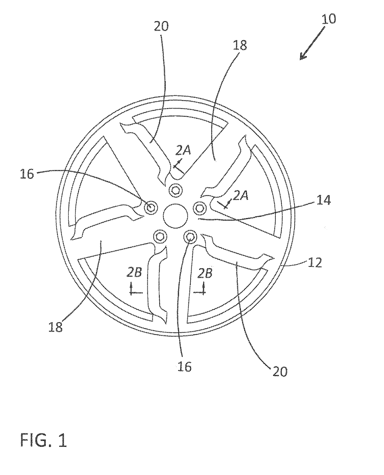
The disclosed inventive concepts provide a wheel that is lighter than known cast aluminum wheels while adding strength, operating efficiency, and design versatility. The wheel is a two-piece wheel with a forged wheel center section and a carbon fiber composite rim that is attached to the cast or forged wheel center section. The spoke design features an airfoil shape that generates airflow during vehicle operation. The wheel insert can be easily replaced by the consumer or off-road vehicles to enhance aesthetic appeal or structural integrity. The wheel insert can also be designed to reduce drag, add down force, and supplement brake system cooling. The patent text also describes a faux bead composite lock ring that protects the composite rim from damage.

Problems solved by technology

For all of their benefits, cast aluminum wheels do present challenges to both manufacturers and designers.
However, wheel stiffness may be sacrificed in the process.
Wheel geometry can be used to improve these properties but casting and subsequent machining of the wheel limit the usefulness of geometry.
For example, it is difficult to make hollow wheel spokes or to create functional shapes that provide aerodynamic benefits.
Customer satisfaction with regard to today's cast aluminum wheel is generally high but dissatisfaction has been expressed over such wheels having poor scratch resistance.
This is particularly frustrating given the considerable expense faced by the consumer in the initial purchase of the cast aluminum wheel.
Over time cast aluminum wheels show damage from contact with curbs, road debris and gravel roads.
However, such clear coat arrangements for wheels have proven to only resist minimal damage before scratching.

Method used


Image

  • Reinforced composite hybrid wheel construction
  • Reinforced composite hybrid wheel construction
  • Reinforced composite hybrid wheel construction

Examples


Embodiment Construction

[0027]In the following figures, the same reference numerals will be used to refer to the same components. In the following description, various operating parameters and components are described for different constructed embodiments. These specific parameters and components are included as examples and are not meant to be limiting.

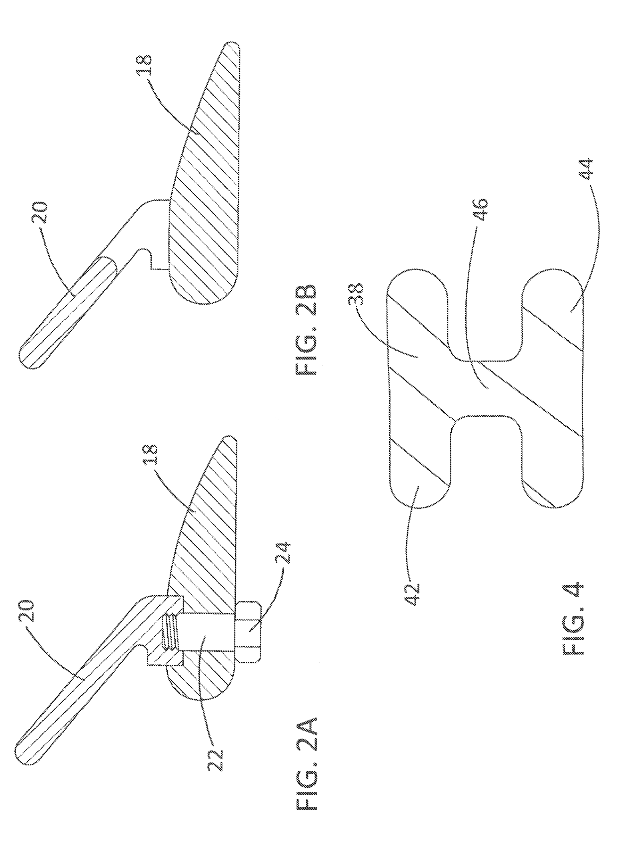
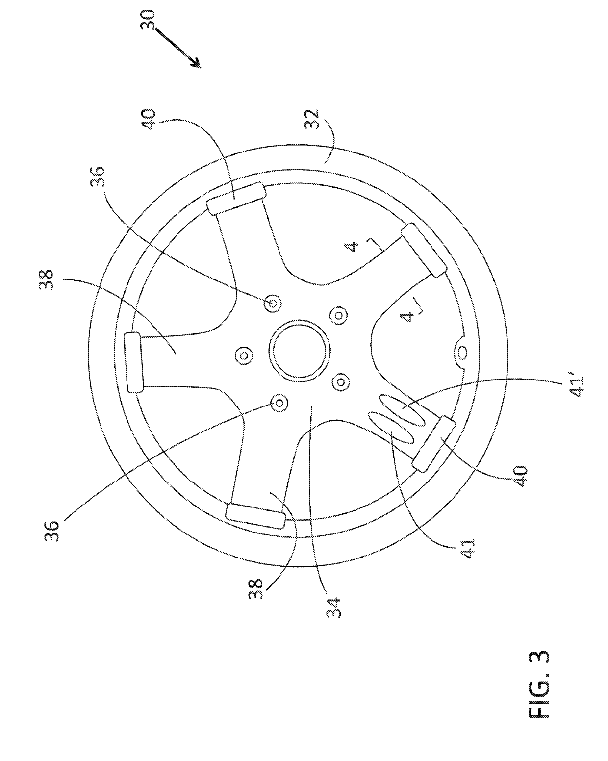
[0028]The accompanying figures and the associated description illustrate the construction alternatives proposed in the disclosed inventive concept of a reinforced composite hybrid wheel that includes various insert attachments and design configurations. In general, FIGS. 1, 2A and 2B relate to a composite hybrid wheel construction that includes airflow-generating wings or wing-like extensions. FIGS. 3 and 4 relate to a composite hybrid wheel construction having a H-beam configuration while FIG. 5 and relate to a composite hybrid wheel construction having a I-beam configuration. Interchangeable inserts for attachment to the wheel spokes are shown in FIGS. 7 ...


PUM

PropertyMeasurementUnit
Angleaaaaaaaaaa
Electrical resistanceaaaaaaaaaa
Shapeaaaaaaaaaa

Abstract

A method and system for improving the strength, functionality and wear-resistance of a composite hybrid wheel is disclosed. Each spoke may define an airfoil shape and have a secondary wing-like extension attached thereto to generate airflow past the vehicle brakes during vehicle operation. Alternatively, the spokes may be shaped in cross-section as either an I-beam or an H-beam configuration. Customer-interchangeable wheel inserts formed from a reinforced polymerized material, such as a long carbon fiber reinforced composite, are strategically attached to one or more of the spokes. The inserts are used to enhance the aesthetic appeal of the wheel, increase its structural integrity and provide easy interchangeability in the event of damage. A faux bead composite lock ring also formed of a reinforced polymerized material such as a long carbon fiber reinforced composite can be attached to the wheel spokes to cover the composite rim flange.

Description

TECHNICAL FIELD[0001]The disclosed inventive concept relates to hybrid vehicle wheels having cast or forged metal centers and with rims composed of a composite material. More particularly, the disclosed inventive concept relates to reinforced hybrid vehicle wheels having spokes of I-beam or H-beam configurations in cross-section. The spokes may alternatively or additionally have airfoil-shapes with secondary wing-like extensions attached thereto to improve cooling airflow to the vehicle's brakes. One or more wheel inserts or segments, including elongated or ring-shaped inserts formed from long fiber composite materials.BACKGROUND OF THE INVENTION[0002]Wheel construction has shown a very wide range of development since the earliest days of vehicle production. Beginning with wooden spokes based on carriage wheels and then on to spokes made of metal, for decades vehicle wheels had been produced from stamped steel. This type of wheel proved both reliable and cost-effective.[0003]However...

Claims


Application Information

Patent Timeline
IPC IPC(8): B60B7/14B60B7/06B60B7/01B60B1/08
CPCB60B7/14B60B7/061B60B7/01B60B1/08B60B5/00B60B2360/3416B60B2900/711B60B3/04B60B21/00B60B5/02B60B7/04B60B7/065B60B2310/305B60B2900/111B60B2900/311Y02T10/86
Inventor FRISKE, DAVID DOUGLASPFEIFFER, JOHN JEFFREY
Owner FORD GLOBAL TECH LLC
Learn More