Seal

a sealing lip and sealing technology, applied in the field of sealing, can solve the problems of being practically impossible to take into account different operating conditions, essentially constant radial force of the power transmission element, and becoming susceptible to defects, so as to reduce the operational wear of the sealing lip and achieve adequate performance characteristics.

Inactive Publication Date: 2010-06-17
CARL FREUDENBERG KG
View PDF0 Cites 8 Cited by
  • Summary
  • Abstract
  • Description
  • Claims
  • Application Information

AI Technical Summary

Benefits of technology

[0004]An general object of the invention is developing a seal of the above-mentioned type in such a way that it features a functionally improved and reliable power transmission element and that its sealing performance and energy due to friction can be dynamically adjusted during the operation of the seal in order to reduce the operational wear of the sealing lip to a minimum while still achieving adequate performance characteristics over a long service life.

Problems solved by technology

The disadvantages of such a power transmission element are that it becomes susceptible to defects when soiling occurs and that the radial force exerted by the power transmission element is essentially constant during the intended use of the seal.
This makes it practically impossible to take into account different operating conditions.
The contact pressure of the sealing lip on the surface to be sealed is generated by the power transmission element and is thus also high, e.g., even when not required for the sealing effect; this creates unnecessarily high friction on the sealing lip during the operation and the resulting heat disadvantageously leads to significant wear of the seal.
However, in contrast, if the known annular coiled spring is realized in such a way that it presses the sealing lip against the surface to be sealed of the machine element to be sealed with only a slight prestress, the risk of leaks is eliminated; but in this case, the performance characteristics are not satisfactory.

Method used


Image

  • Seal
  • Seal
  • Seal

Examples


Embodiment Construction

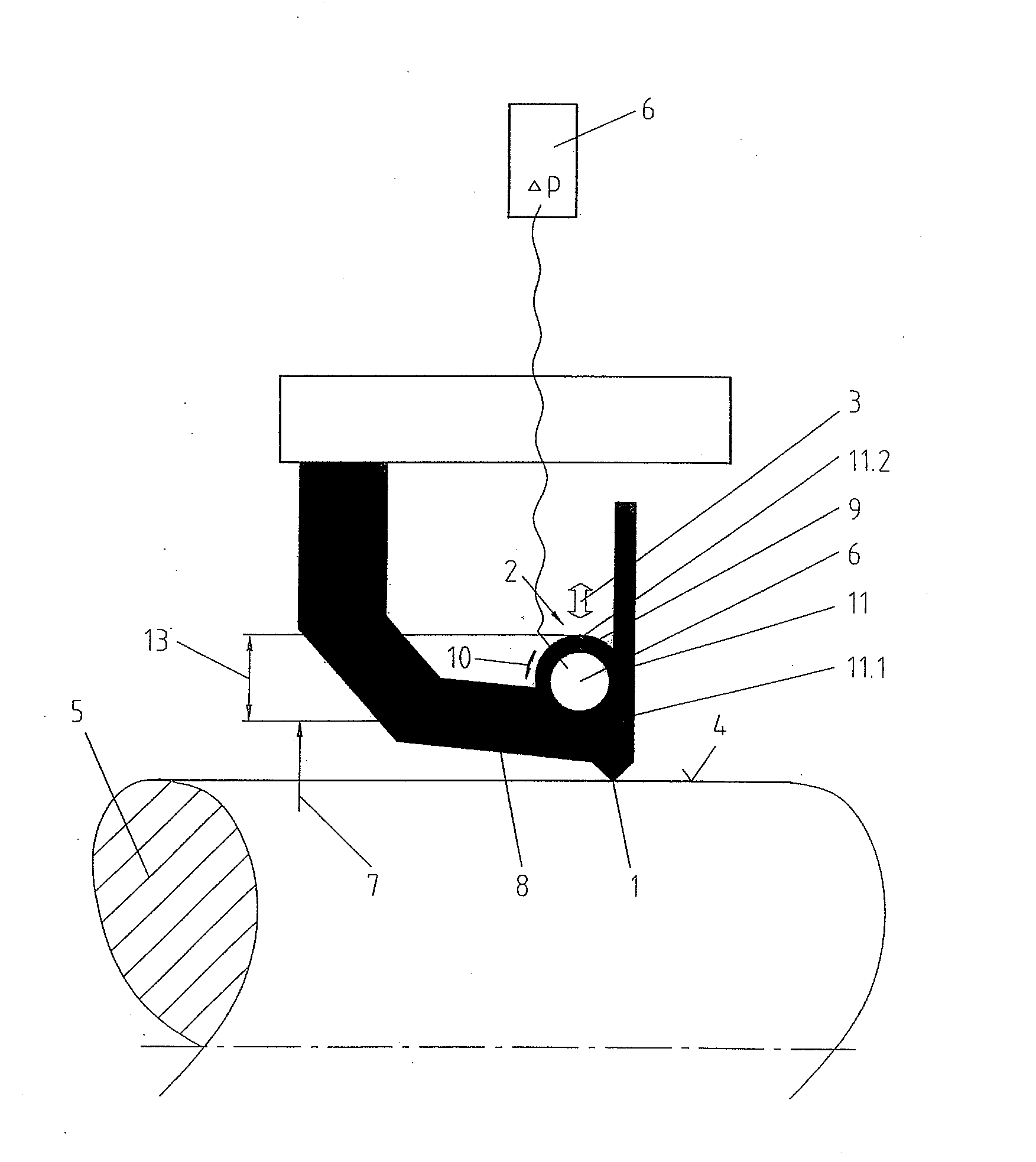
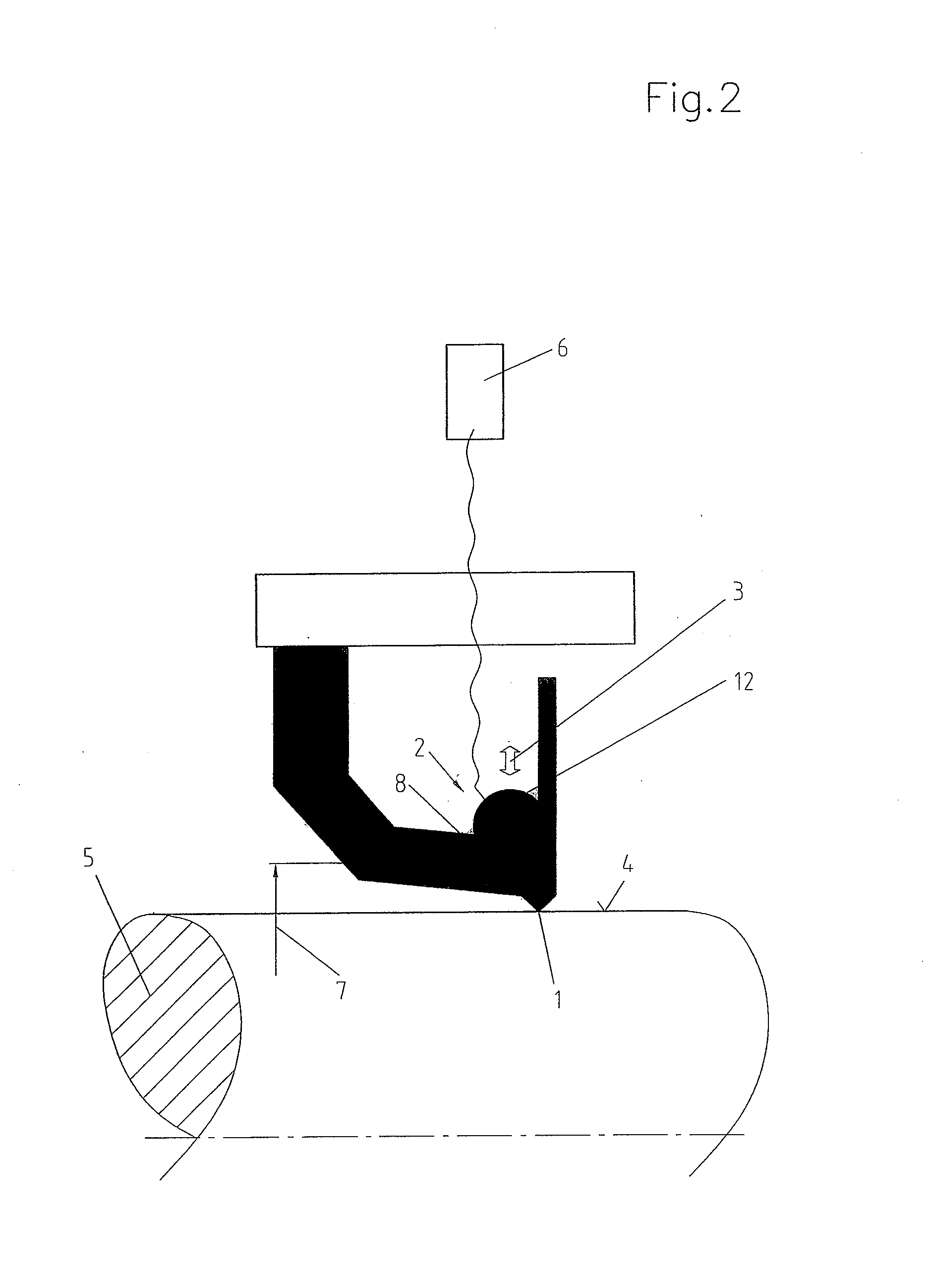
[0028]FIGS. 1 to 3 respectively show exemplary embodiments of a seal of the invention, wherein the power transmission elements 2 are respectively realized in different ways. The two seals are respectively realized in the form of radial shaft ring seals with a dynamically stressed sealing lip 1 of elastomer material that encloses the surface to be sealed 4 of a machine element 5 to be sealed, in this case, a shaft, in a sealing manner under radial prestress.

[0029]According to the invention, it is proposed that the effective diameter 7 of the power transmission element 2 be adjusted in the radial direction 3 of the seal with the aid of an adjusting mechanism 6 while the seal is in use. The actuation of the adjusting mechanism 6 makes it possible to adjust to a larger or smaller effective diameter 7 of the power transmission element 2 depending upon the given circumstances of the application and the operating conditions.

[0030]In all exemplary embodiments, the effective diameter 7 can b...


PUM


Abstract

The invention pertains to a seal with at least one sealing lip that can be pressed against a surface to be sealed of a machine element to be sealed in the radial direction by means of an annular power transmission element. The power transmission element has an effective diameter that can be varied on both sides in the radial direction with the aid of an adjusting mechanism.

Description

FIELD OF THE INVENTION[0001]The invention pertains to a seal with at least one sealing lip that can be pressed against a surface to be sealed of a machine element to be sealed in the radial direction by means of an annular power transmission element.BACKGROUND OF THE INVENTION[0002]A seal of the above-mentioned type is generally known and realized, for example, in the form of a radial shaft ring seal. In this case, the power transmission element is realized in the form of an annular coiled spring of a metallic material and ensures that the sealing lip of the seal is always tightly pressed against the surface to be sealed during its intended use. The annular coiled spring is intended to compensate for relaxations of the elastomer material of the sealing lip and its wear during use and also to ensure a reliable seal if the space to be sealed is subjected to only relatively low excess pressure that by itself would not sufficiently press the sealing lip against the surface to be sealed ...

Claims


Application Information

Patent Timeline
Patent Type & Authority Applications(United States)
IPC IPC(8): F16J15/32F16J15/16
CPCF16J15/3208F16J15/3212F16J15/46F16J15/3296F16J15/322
Inventor SCHMIED, BENNOMULLER-NIEHUSS, KRISTIANSCHAUBER, THOMAS
Owner CARL FREUDENBERG KG
Why Eureka
Try Eureka