System and method for a flyable and roadable vehicle

a technology applied in the field of flying and roadable vehicles, can solve the problems of high-speed propeller rotation and foreign object entrainment, and would be a road hazard to other vehicles and pedestrians, and achieve the effects of reducing the effect of cross-wind, reducing the gravity center of the vehicle, and facilitating operation

Inactive Publication Date: 2011-01-25
XU JUNFENG
View PDF21 Cites 36 Cited by
  • Summary
  • Abstract
  • Description
  • Claims
  • Application Information

AI Technical Summary

Benefits of technology

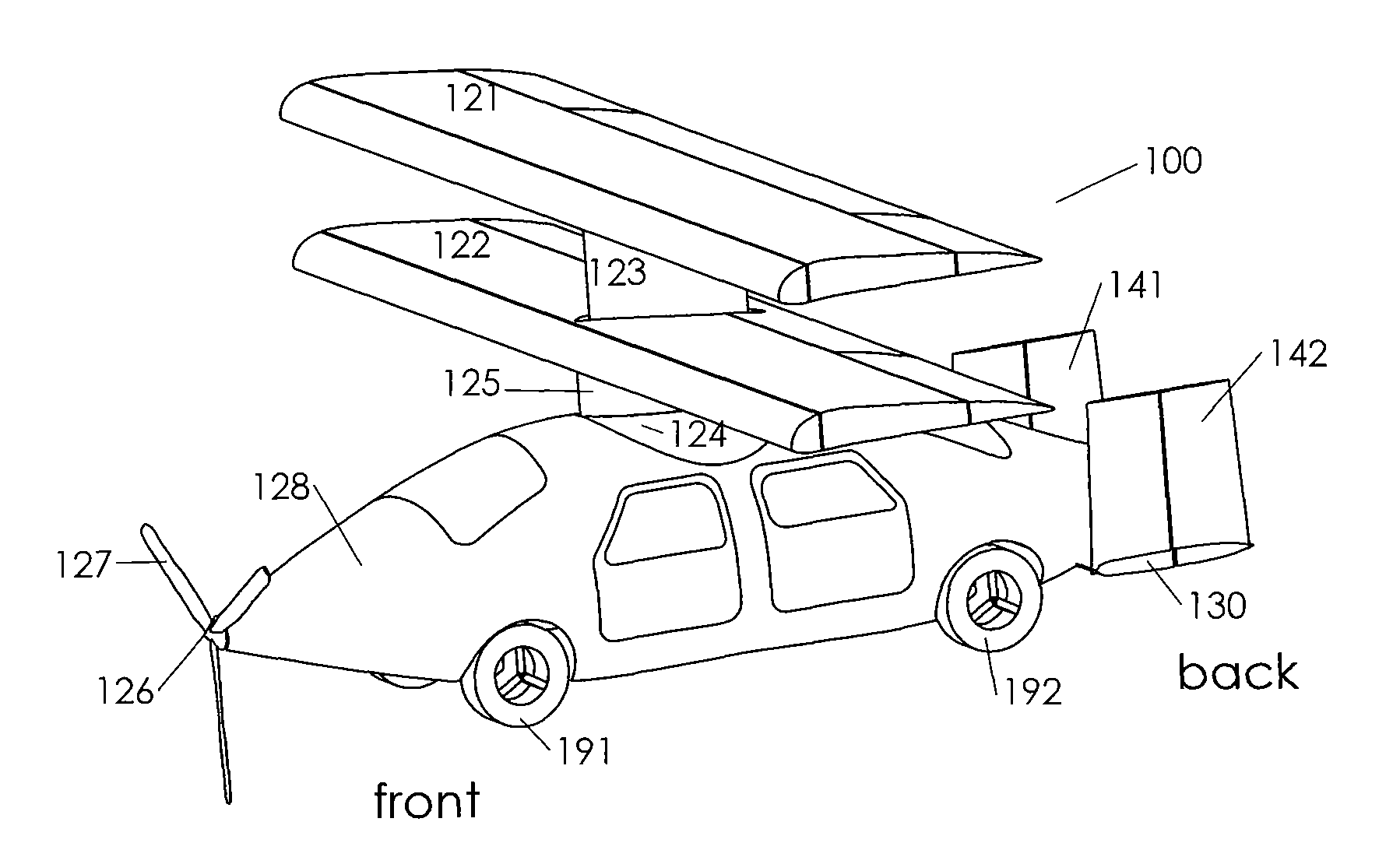
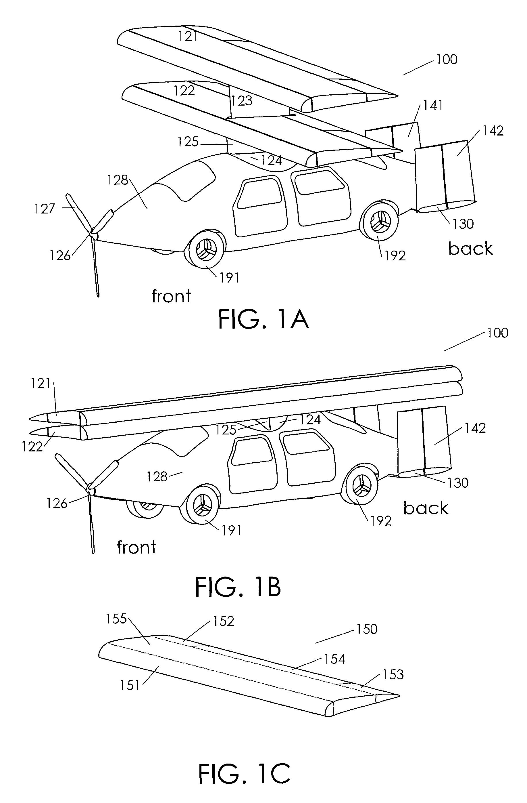
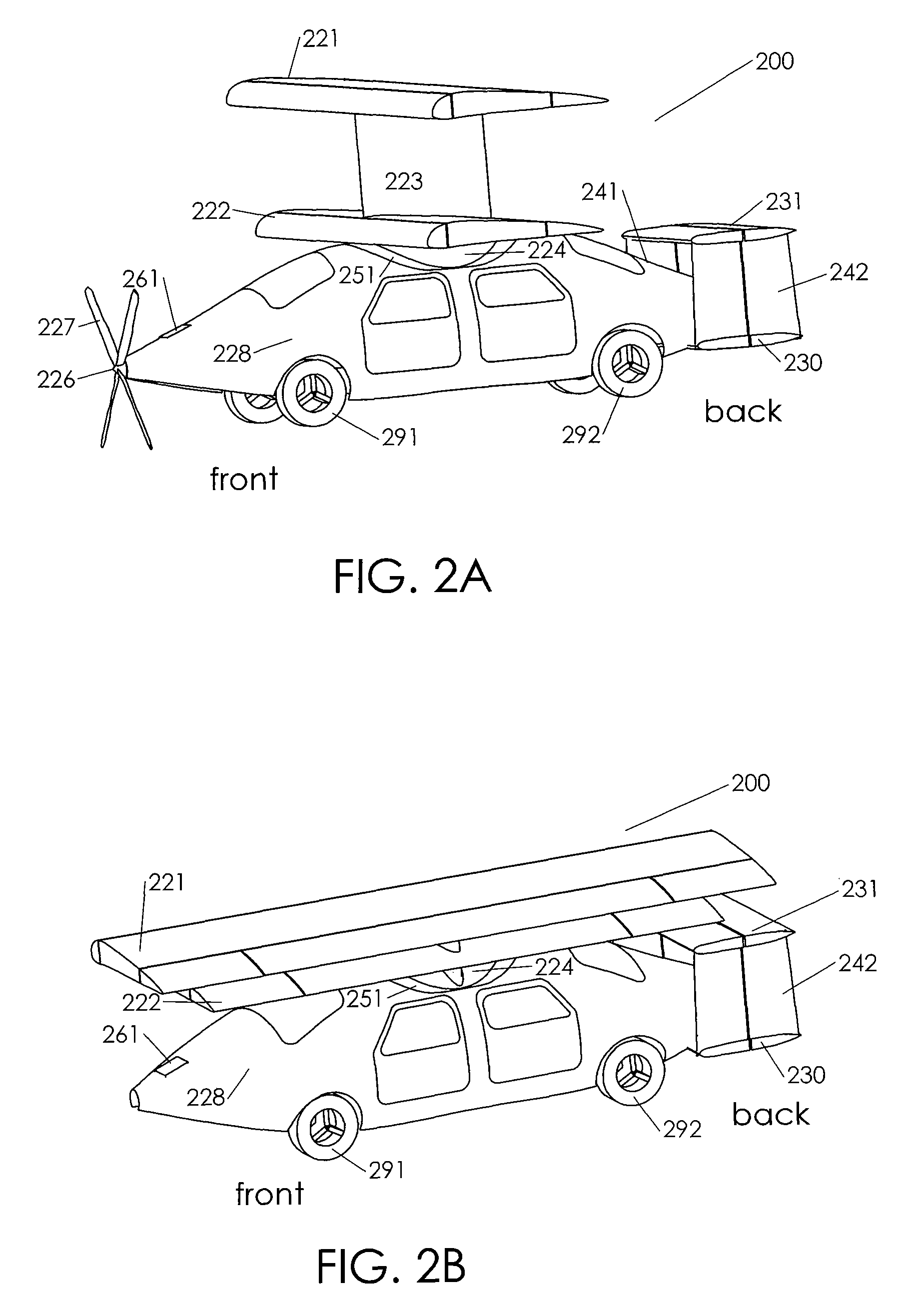
[0011]A vehicle that can be used for air and high speed road travel. It has an integrated multi-plane wing. The multi-plane wing is mostly parallel to the longitudinal axis of the fuselage in road travel, and mostly transverse in air travel. The heights of some or all planes of the wings could be lowered in ground travel to lower the gravity center of the vehicle and to reduce the effect of cross-wind. The wing is changed between these two positions during travel mode transition, preferably by automatic mechanism to ease the operation and reduce the chance of human errors. The multi-plane structure significantly increases the total lifting area while keeps the projected wing area small. The one-piece construction of the wing lowers its weight, manufacture difficulty and cost, improves its structural strength, and reduces operational wear. It also facilitates the integration of flight control systems, including ailerons, flaps, slats, airbrakes, and sometimes wingtip rudders. In addition, it is to be appreciated that existing configurations on the wing, such as winglet, can be integrated easily.
[0012]Another objective of this invention is to provide a propulsion mechanism for the vehicle. Propeller propulsion by piston engines is the preferred choice for air travel due to its low cost, although jet engine propulsion is also compatible with such a vehicle. The propeller could be either in the front or at the rear of the vehicle, normally referred to as puller and pusher, or a combination of both. The combination scheme, with one propeller at the front and another one at the rear, allows each propeller to be smaller and shorter for the same total propulsion force. It also provides redundancy and improves the safety factor in the event of single propeller / engine failure. For road travel, the propulsion is preferably delivered to the wheels thru transmission systems. Propeller propulsion for road travel could cause foreign object entrainment, and the high speed propeller rotation would be a road hazard to other vehicles and pedestrians. The vehicle could have three or four, or even more wheels. The four wheel option is preferred for its stability and proven high speed highway performance.
[0013]Yet another objective of this invention is to increase the unblocked visual field for road travel. The propellers could have two blades or more. In the case of two blades, the blades are preferred to be in a horizontal position for road travel to clear the visual field for the driver. In the case of three blades, one of the blades would be pointing straight down for road travel; in the case of four blades, the blades will point in a direction that is 45 degree away from horizontal. These orientations increase the unblocked visual field for the driver. The blade could also be made of transparent material to enhance driver visibility. Similarly, the end portions of the multi-plane wing, which are on top of the vehicle for road travel, can be also made transparent to ease the visual observation of high road signs and traffic lights.
[0014]Yet another approach is to install a visual sensor like video camera at the front of the vehicle, and relay the image to the driver. Similar relayed video images could be used for rear and side views. Bending the outer portions of the planes of wings upward also allows better visual field. Other approaches include a reflecting mirror in the front portion of fuselage to allow the driver to read the traffic signs. The pusher configuration, which doesn't have a propeller in the front and allows the driver seat to be closer to the front of the vehicle, is especially attractive for a wide visual field. A combination of the techniques mentioned can be applied to effectively increase unblock visual field, including the front, rear and side views.
[0019]Many benefits are achieved by way of the present invention over conventional techniques. For example, the present technique provides a roadable aircraft that is reliable, convenient, and economical. Compared to conventional designs, roadable aircraft according to the embodiment of the present invention is easy to manufacture, has high strength and light weight, and integrates conventional flight control elements. For example, embodiments of the present invention is suitable for average consumers, and can be used to significantly shorten the time for medium to long range travel. Depending upon the embodiment, one or more of these benefits may be achieved. These and other benefits will be described in more details throughout the present specification, particularly below.

Problems solved by technology

Propeller propulsion for road travel could cause foreign object entrainment, and the high speed propeller rotation would be a road hazard to other vehicles and pedestrians.

Method used


Image

  • System and method for a flyable and roadable vehicle
  • System and method for a flyable and roadable vehicle
  • System and method for a flyable and roadable vehicle

Examples


Embodiment Construction

[0028]The present invention is directed to flyable and roadable vehicles and the use thereof. More particularly, the invention provides a method and system for flight capable vehicles that are suitable for both land and air traveling. Merely by way of example, the invention has been applied to the dual use vehicles with alternative operation modes and configurations. But it would be recognized that the invention has a much broader range of applicability.

[0029]As explained above, vehicles that are capable of both land and air travel have been an aspiration for generations of aviators. In the mass media, this type of vehicles has been referred to as roadable aircrafts, roadable personal air vehicles, flying cars, etc. Typically, this type of vehicle is capable of legally travel on the road and can also be used as aircrafts. It is to be understood the vehicles according to embodiments of the present invention have a wide range of applications and should not be limited to the abovementi...


PUM


Abstract

System and method for a flyable and roadable vehicle. According to an embodiment, the present invention provides a vehicle capable of air and road travel. The vehicle is adaptable to a flying configuration and a road configuration. The vehicle includes a fuselage having a front end, a rear end, a top side, a bottom side. The vehicle also includes a wing component having a plurality of planes. The plurality of planes includes a first plane and a second plane. The vehicle additionally includes a connecting component for coupling the planes of the wing and the fuselage. The connecting component is able to accommodate a substantial relative rotation between the first plane and the fuselage. The vehicle further includes a plurality of wheels coupled to the bottom side of the fuselage.

Description

CROSS-REFERENCES TO RELATED APPLICATIONS[0001]This application claims priority to U.S. Provisional Patent Application No. 60 / 830,650 filed Jul. 12, 2006 titled “Dual Use Vehicle” by inventor Junfeng Xu, which is incorporated by reference herein for all purposes.[0002]The application additionally claims priority to U.S. Provisional Patent Application No. 60 / 832,335 filed on Jul. 22, 2006 titled “Dual Use Vehicle” by inventor Junfeng Xu, which is incorporated by reference herein for all purposes.STATEMENT AS TO RIGHTS TO INVENTIONS MADE UNDER FEDERALLY SPONSORED RESEARCH OR DEVELOPMENT[0003]Not ApplicableREFERENCE TO A “SEQUENCE LISTING,” A TABLE, OR A COMPUTER PROGRAM LISTING APPENDIX SUBMITTED ON A COMPACT DISK[0004]Not ApplicableBACKGROUND OF THE INVENTION[0005]The present invention is directed to flyable and roadable vehicles and the use thereof. More particularly, the invention provides a method and system for vehicles that are suitable for both land and air traveling. Merely by ...

Claims


Application Information

Patent Timeline
Patent Type & Authority Patents(United States)
IPC IPC(8): B64C37/02B64D5/00
CPCB60F5/02B64C37/00
Inventor XU, JUNFENG
Owner XU JUNFENG
Why Eureka
Try Eureka