Gimbal handheld holder

a handheld gimbal and handheld technology, applied in the field of gimbal handheld holder, can solve the problems of inconvenient use and installation, inability to control, and only hand-held handheld gimbals, and achieve the effects of convenient installation, enhanced use convenience, and large volume and weigh

Active Publication Date: 2018-01-25
YUNEEC TECH CO LTD
View PDF5 Cites 3 Cited by
  • Summary
  • Abstract
  • Description
  • Claims
  • Application Information

AI Technical Summary

Benefits of technology

[0024]Positive progress effects of the present invention of the present invention are as follows. The present invention achieve force balance at two ends of the gimbal handheld holder, and steadily holds the gimbal below the transverse rod, and especially for the gimbal with larger volume and weight, the support effect of the present invention is better; while ...

Problems solved by technology

Existing handheld gimbals are only hand-held and unable to be controlled.
Moreover, no support portion is provided in the existing handheld gimbals...

Method used


Image

  • Gimbal handheld holder
  • Gimbal handheld holder
  • Gimbal handheld holder

Examples


first embodiment

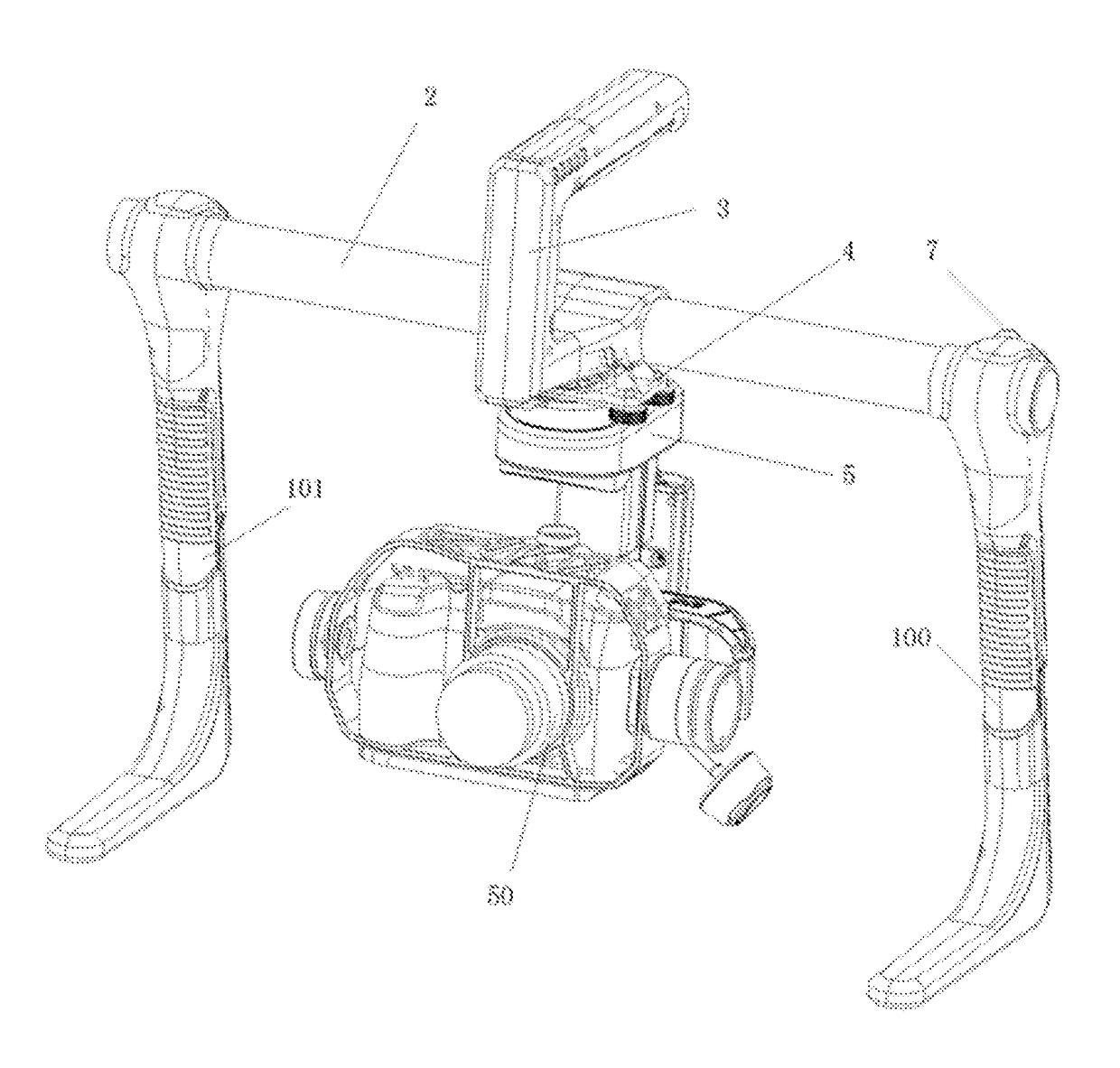
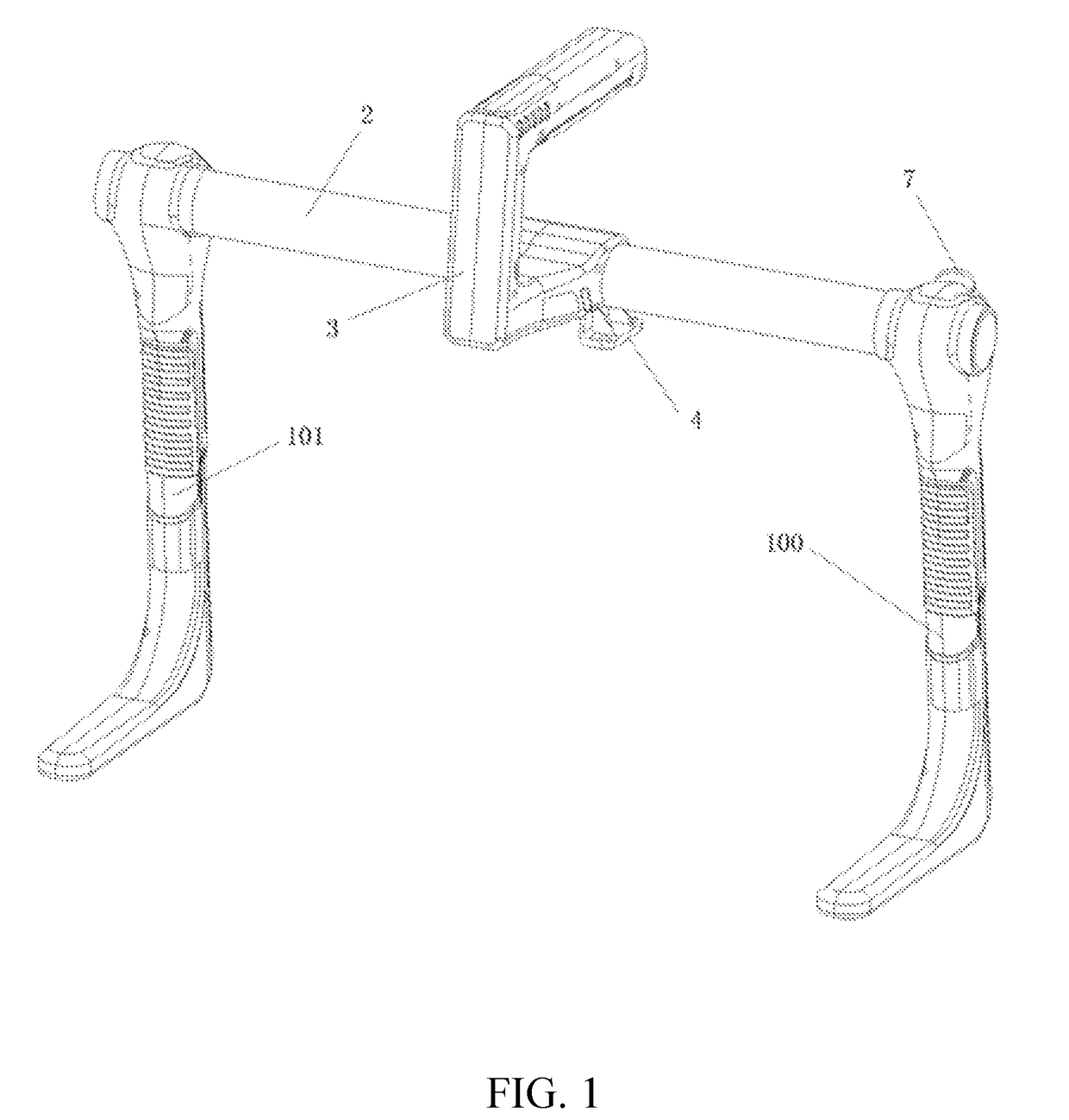
[0033]This embodiment provides a gimbal handheld holder, as shown FIGS. 1-3, which comprises two support legs 100, 101 and a control device, wherein a transverse rod 2 is located between the two support legs 100, 101; a handle 3 is located on the transverse rod 2; a gimbal connector 4 is located at a junction of the handle 3 with the transverse rod 2; the gimbal handheld holder is connected with a gimbal 5 through the gimbal connector 4; the gimbal 5 is located below the transverse rod 2 and between the two support legs 100, 101; the handle 3 is located on the transverse rod 2; and the control device is adapted for controlling the gimbal 5 to move.

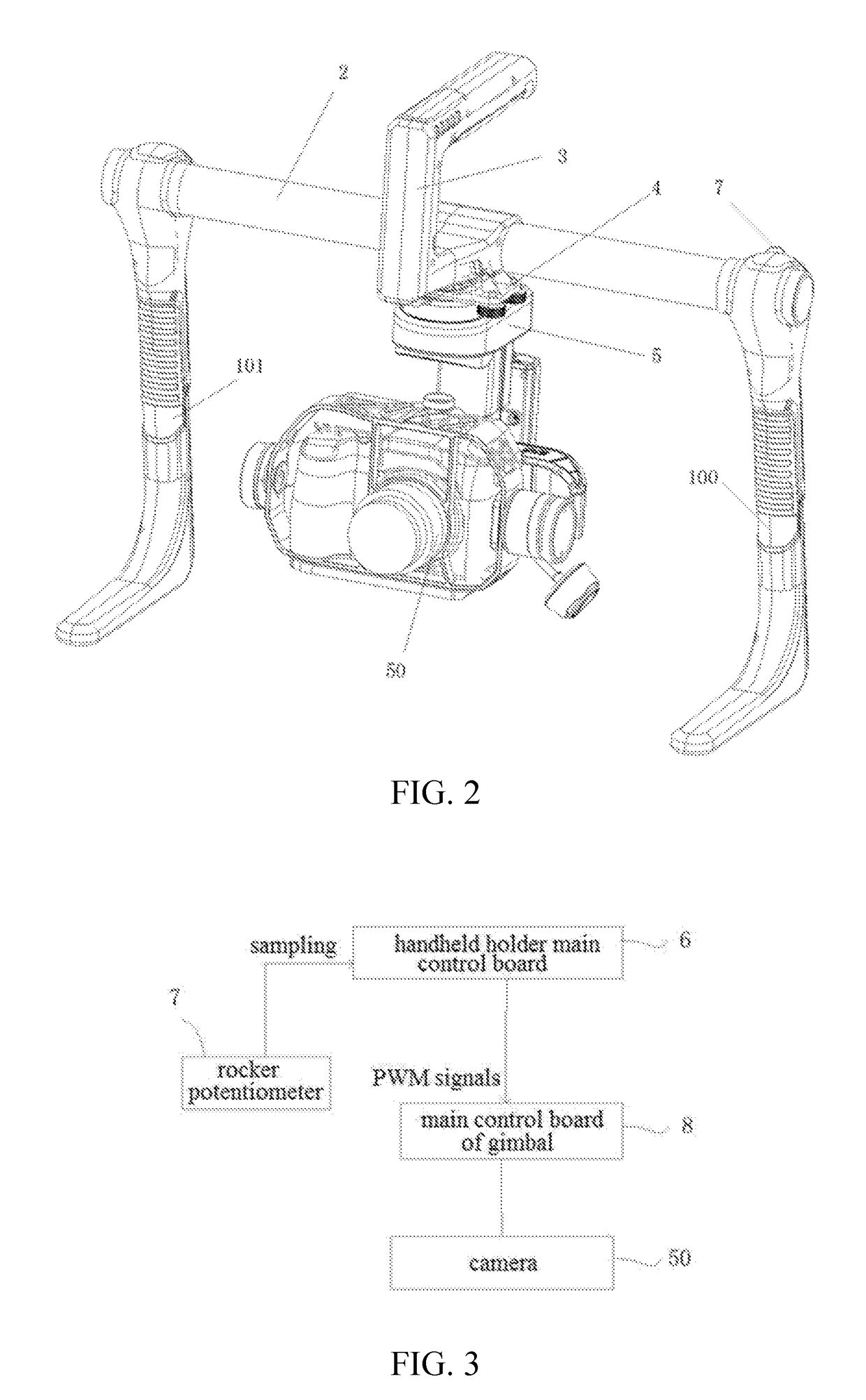
[0034]A camera device is located on the gimbal, such as a vidicon or a camera, which is able to capture pictures. In this embodiment, a camera 50 is located on the gimbal. The control device comprises a handheld holder main control board 6 and a rocker potentiometer 7, wherein the handheld holder main control board 6 is located within the ...

second embodiment

[0037]This embodiment provides a gimbal handheld holder, as shown in FIG. 4, which is different from the first embodiment as follows. In this embodiment, the gimbal handheld holder further comprises another rocker potentiometer 70 located on the right support leg 101, wherein the rocker potentiometer 70 controls a pitch direction of the gimbal, in such a manner that the gimbal rotates around X-axis, which defines a pitch angle, that is, the gimbal rotates clockwise or anticlockwise in a direction perpendicular to a horizontal plane, and the lens of the corresponding camera rotatably shoots upwardly or downwardly in the direction perpendicular to the horizontal plane.

[0038]In actual control, electrical signals of the rocker potentiometer 70 are sampled, wherein an amount of samples is in a range of 0-1023. Through the way of filtering and angle conversion, the handheld holder main control board 6 obtains the PWM signals with a high level time of 1-2 ms. In this embodiment, 1023 sampl...

third embodiment

[0040]This embodiment provides a gimbal handheld holder, as shown in FIG. 5, which is different from the first embodiment as follows. In this embodiment, the rocker potentiometer 7 is also able to control a pitch direction of the gimbal, a control principle is same as the second embodiment, that is to say, two electrical signals of the rocker potentiometer 7 are sampled, which comprises an electrical signal for controlling the yaw direction and an electrical signal for controlling the pitch direction, the handheld holder main control board 6 finally sends two PWM signals to the main control board 8 of the gimbal 5, so as to achieve the rotation of the gimbal in the yaw and pitch directions. In actual operation, the rocker potentiometer 7 is operated up and down to control the pitch direction of the gimbal, namely, in this embodiment, the functions of controlling the gimbal to rotate in two directions are centered on one rocker potentiometer 7, thus saving development costs and simpl...


PUM


Abstract

A gimbal handheld holder includes two support legs (100, 101) and a control device. A transverse rod (2) is located between the two support legs (100). A handle (3) is located on the transverse rod (2). A gimbal connector (4) is located at a junction of the handle (3) with the transverse rod (2). The gimbal handheld holder is connected with a gimbal (5) through the gimbal connector (4). The gimbal (5) is located below the transverse rod (2) and between the two support legs (100). The handle (3) is located on the transverse rod (2). The control device controls the gimbal (5) to move. The gimbal handheld holder is able to achieve force balance at two ends thereof, and steadily hold the gimbal below the transverse rod. While being connected with the gimbal, the gimbal handheld holder is able to be directly steadily placed on ground. Moreover, the gimbal handheld holder includes the control device and adopts different control method to improve control flexibility for the gimbal.

Description

CROSS REFERENCE OF RELATED APPLICATION[0001]This is a U.S. National Stage under 35 U.S.C 371 of the International Application PCT / CN2016 / 079045, filed Apr. 12, 2016, which claims priority under 35 U.S.C. 119(a-d) to CN 201510172556.3, filed Apr. 13, 2015; and CN 201520219738.7, filed Apr. 13, 2015. All contents of the priority document are included into this application by reference.BACKGROUND OF THE PRESENT INVENTIONField of Invention[0002]The present invention relates to a gimbal handheld holder.Description of Related Arts[0003]Existing handheld gimbals are only hand-held and unable to be controlled. A camera is placed on the gimbal, so it is required for a control device to control the gimbal for achieving shooting without a dead angle, so as to accurately adjust the photographing angle. Moreover, no support portion is provided in the existing handheld gimbals, so that the handheld gimbals are unable to be placed on ground or a plane while being connected, thus the usage and the ...

Claims


Application Information

Patent Timeline
IPC IPC(8): F16M11/18H04N5/225H04N5/232F16M11/12F16M13/04
CPCF16M11/18F16M11/123F16M13/04H04N5/23296H04N5/2252F16M11/10F16M11/2071F16M11/22F16M2200/08G03B17/563F16M13/00H04N23/51H04N23/69
Inventor TIAN, YUJIANG, WENYAN
Owner YUNEEC TECH CO LTD
Why Eureka
Try Eureka