Backrest device

Inactive Publication Date: 2010-06-17
YANG PO HSUAN
View PDF5 Cites 13 Cited by
  • Summary
  • Abstract
  • Description
  • Claims
  • Application Information

AI Technical Summary

Benefits of technology

[0007]When the user sits in the chair with his back leaning against the backrest, since the springs are flexible, which can enable the backrest to be freely adjusted and moved

Problems solved by technology

Usually, a conventional backrest for a chair is unmovable, when the user sits on the chair, the back of the u

Method used


Image

  • Backrest device
  • Backrest device
  • Backrest device

Examples


Embodiment Construction

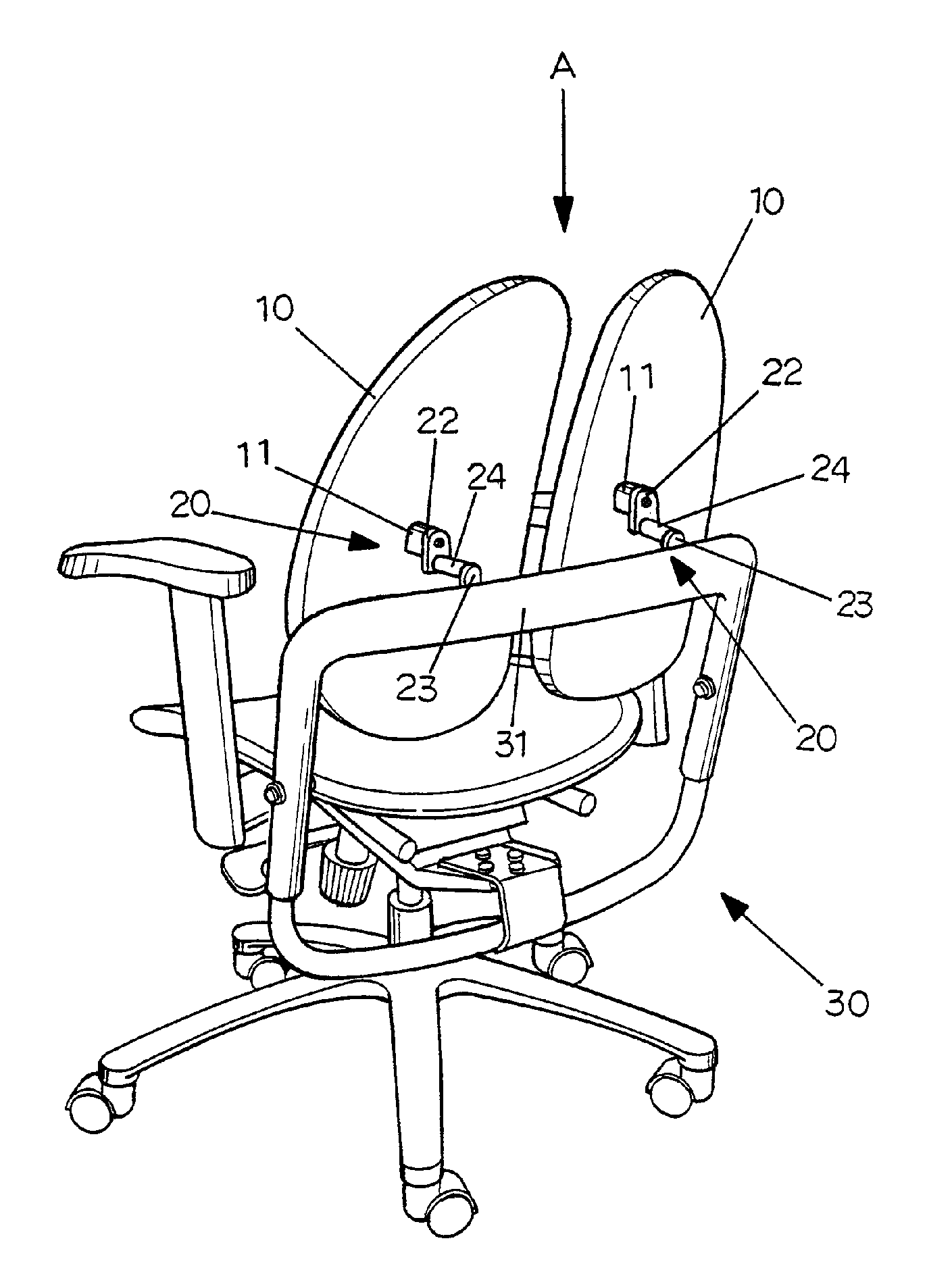
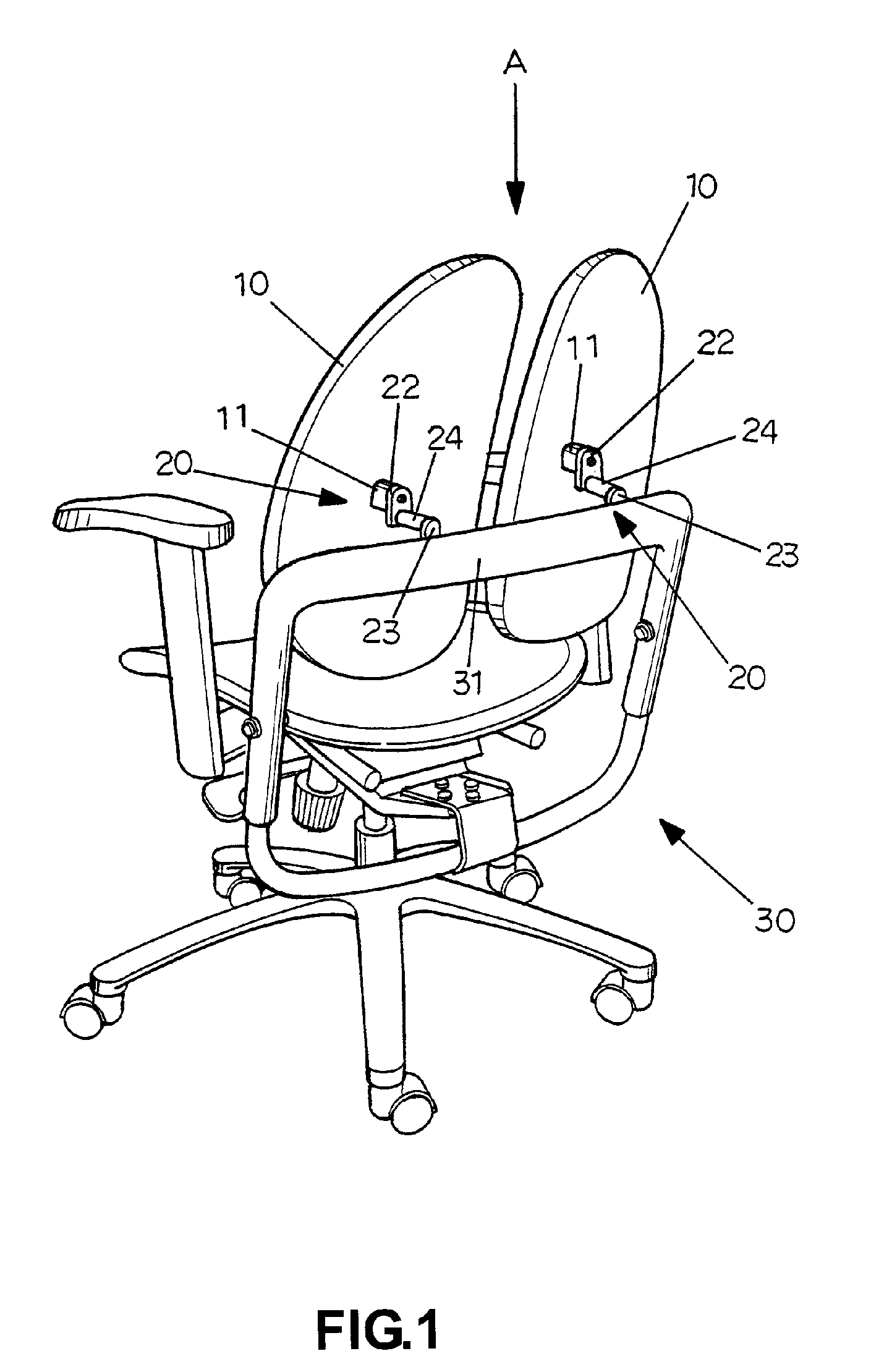
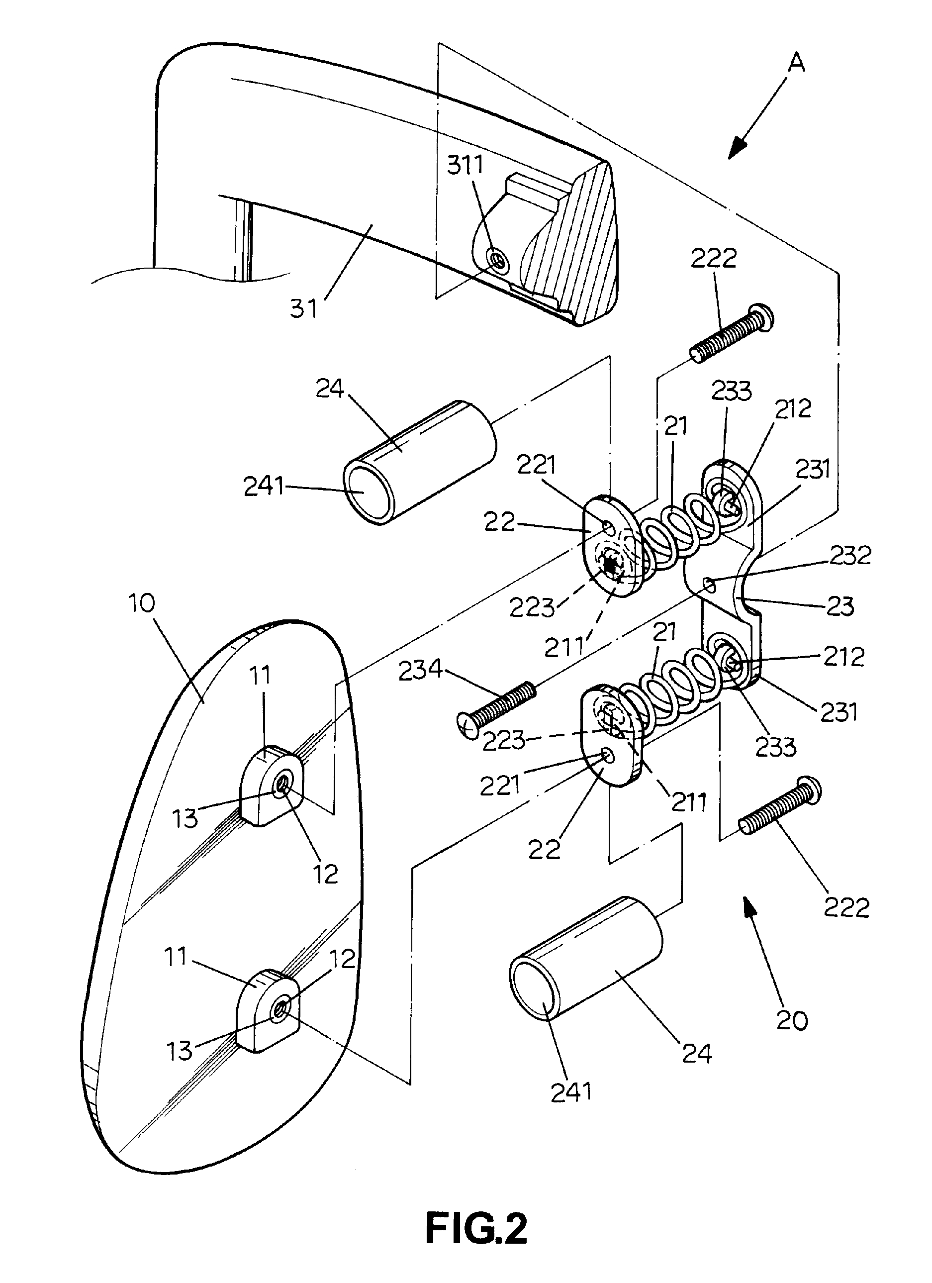
[0016]Referring to FIGS. 1-3, a backrest device A in accordance with the present invention is assembled to a chair that can be an ordinary chair, a vehicle chair, an office chair or other chairs, and the backrest device A in accordance with a first embodiment of the present invention is assembled to the office chair 30.

[0017]The backrest device A comprises at least one backrest 10 and at least one connecting unit 20.

[0018]On a rear surface of the backrest 10 is provided with two positioning blocks 11, and each positioning block 11 is provided with a threaded sleeve 13 having an inner threaded portion 12.

[0019]The connecting unit 20 comprises two springs 21, two jointing members 22, a connecting member 23 and two mounting members 24.

[0020]Each spring 21 is flexible and comprises a first end 211 and a second end 212 arranged in a reverse direction to the first end 211.

[0021]Each jointing member 22 is defined with a through hole 221 through which a threaded member 222 is threaded in th...


PUM


Abstract

A backrest device comprises at least one backrest and at least one connecting unit having two springs, two jointing members and a connecting member. Each spring comprises a first end and a second end. Each jointing member is provided with at least one first engaging block for engaging with the first end of the spring. The connecting member is provided with at least one second engaging block for engaging with the second end of the spring and is fixed to a chair stably. When the user sits in the chair with his back leaning against the backrest, since the springs are flexible, which can enable the backrest to be freely adjusted and moved in response to the movement of the back of the user, producing a buffering effect and providing a comfortable support to the back of the user, so the user will feel comfortable.

Description

BACKGROUND OF THE INVENTION[0001]1. Field of the Invention[0002]The present invention relates to a backrest device, and more particularly to a backrest device which is assembled to a chair, so as to enable the backrest device to be freely adjusted and moved in response to the movement of the back of the user.[0003]2. Description of the Prior Art[0004]Usually, a conventional backrest for a chair is unmovable, when the user sits on the chair, the back of the user is abutted against the fixed backrest and repressed by the backrest, so the user will feel uncomfortable.[0005]The present invention has arisen to mitigate and / or obviate the afore-described disadvantages.SUMMARY OF THE INVENTION[0006]The primary objective of the present invention is to provide a backrest device comprising at least one backrest and at least one connecting unit. On a rear surface of the backrest is provided with two positioning blocks. The connecting unit comprises two springs, two jointing members and a conne...

Claims


Application Information

Patent Timeline
IPC IPC(8): A47C7/40
CPCA47C7/443A47C7/405
Inventor YANG, PO HSUAN
Owner YANG PO HSUAN
Why Eureka
Try Eureka