
Backlight Device, Display Device, and Television Receiver

a technology of display device and backlight device, which is applied in the direction of static indicating device, television system, instruments, etc., can solve the problems of direct type backlight device having a hollow structure and therefore being light-weight, and achieve the effect of improving display performan

Inactive Publication Date: 2010-06-17
SHARP KK
View PDF5 Cites 8 Cited by
  • Summary
  • Abstract
  • Description
  • Claims
  • Application Information

AI Technical Summary

Benefits of technology

[0020]The present invention can provide a backlight device that can prevent the occurrence of nonuniform brightness and flickers even if the display performance is improved, and a display device and a television receiver that use the backlight device.

Problems solved by technology

Furthermore, the direct type backlight device has a hollow structure and therefore is light-weight even if it is enlarged.

Method used


Image

  • Backlight Device, Display Device, and Television Receiver
  • Backlight Device, Display Device, and Television Receiver
  • Backlight Device, Display Device, and Television Receiver

Examples


first embodiment

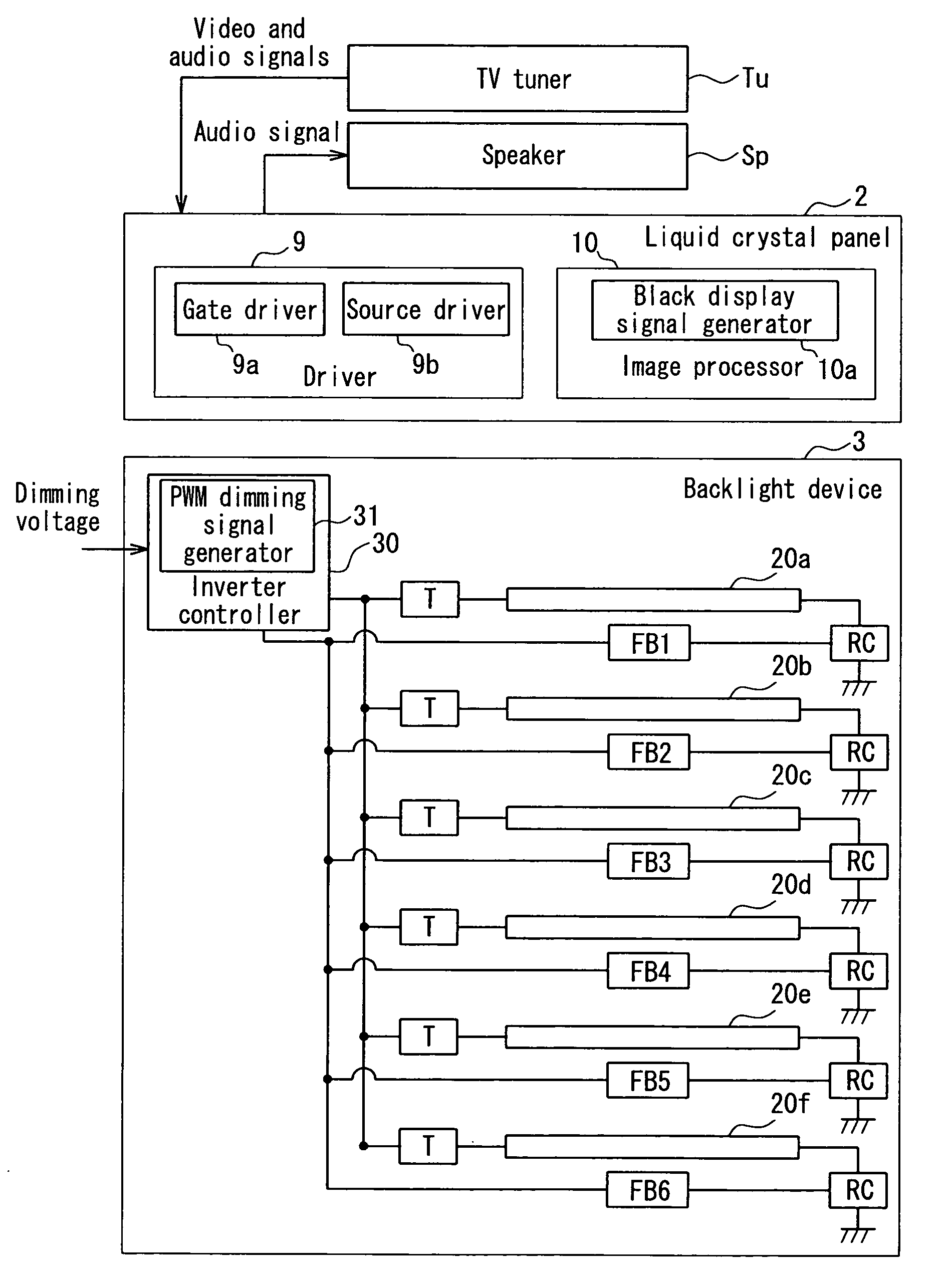
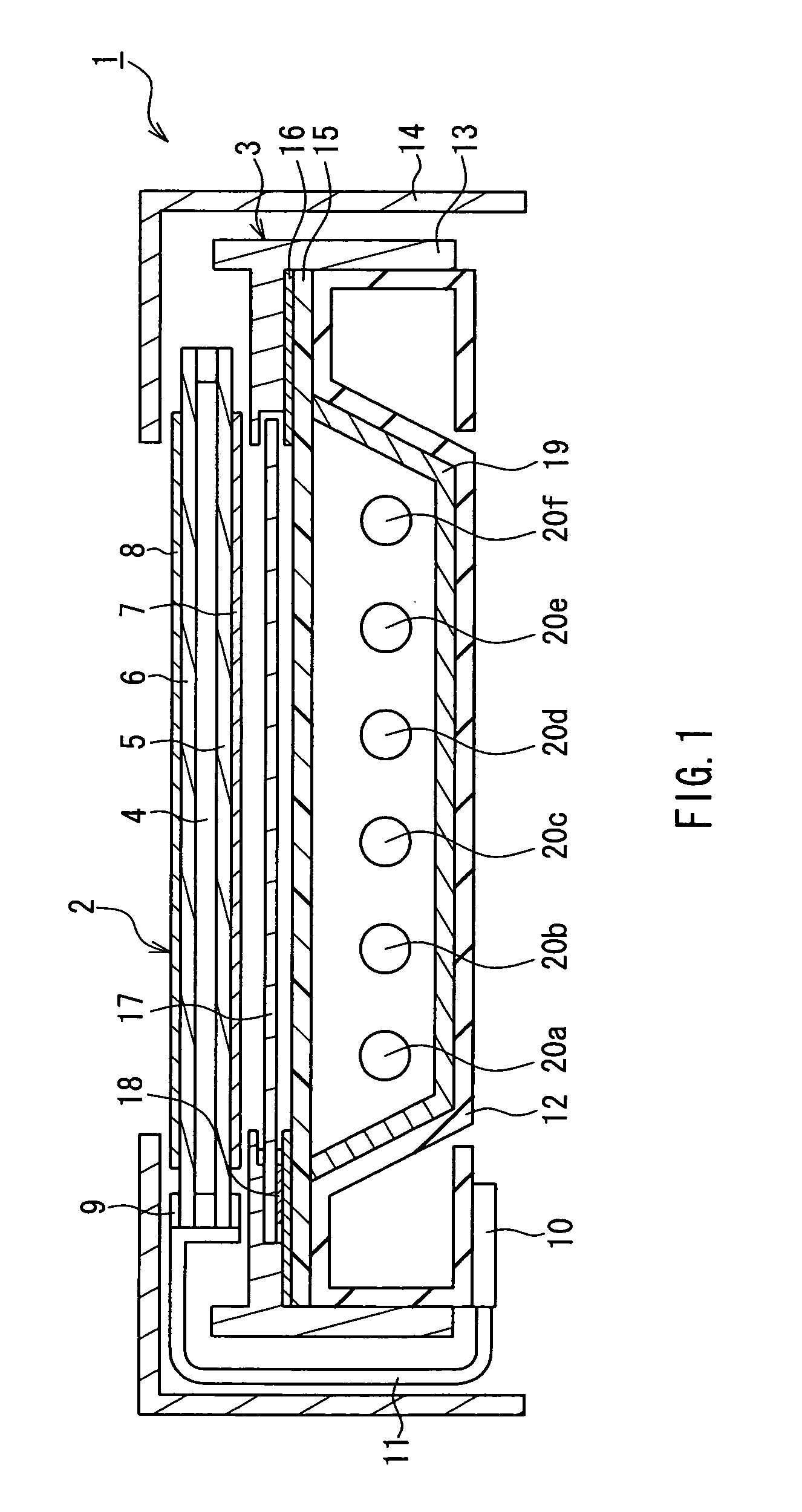
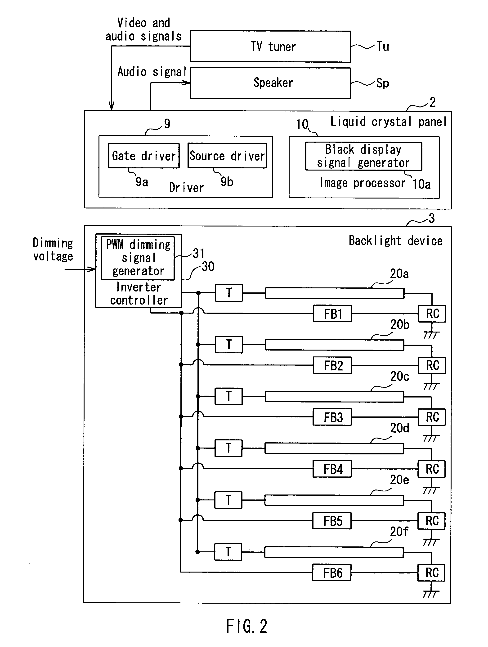
[0028]FIG. 1 is a schematic cross-sectional view illustrating a backlight device and a liquid crystal display device (television receiver) according to a first embodiment of the present invention. In FIG. 1, a liquid crystal display device 1 of this embodiment includes a liquid crystal panel 2 as a display portion that is placed so that the upper side of the figure is a viewer side (i.e., a display surface side), and a backlight device 3 of the present invention that is placed on a non-display surface side of the liquid crystal panel 2 (i.e., the lower side of the figure) and generates illumination light for illuminating the liquid crystal panel 2. In the liquid crystal display device 1, as shown in FIG. 2, a TV tuner Tu that receives video and audio signals of a television broadcast and a speaker Sp that reproduces and outputs audio signals are connected to the liquid crystal panel 2 side, and thus the liquid crystal display device 1 functions as a liquid crystal television.

[0029]T...

second embodiment

[0046]FIG. 5 is a plan view showing lamp units provided in a backlight device according to a second embodiment of the present invention. In FIG. 5, this embodiment mainly differs from the first embodiment in that the lamp units including a pseudo U-shaped tube are used in place of the light source units each of which includes a single cold-cathode tube and a CCFL driving circuit connected in series with the cold-cathode tube. The same components as those in the first embodiment are denoted by the same reference numerals, and the explanation will not be repeated.

[0047]As shown in FIG. 5; in the backlight device 3 of this embodiment, lamp units 40a, 40b, and 40c are set on a reflection sheet 19. Each of the lamp units 40a to 40c includes a pair of cold-cathode tubes 41, 42 and a connection wiring 43 for electrically connecting the pair of cold-cathode tubes 41, 42. In this configuration, a pseudo U-shaped tube is used to simulate a U-shaped tube. Furthermore, each of the lamp units 40...


PUM


Abstract

In one embodiment of the present invention, a backlight device includes six light source units including cold-cathode tubes (linear light sources) and driving circuits for driving the respective cold-cathode tubes. The light source units are arranged in a direction perpendicular to a longitudinal direction of the cold-cathode tubes. In one embodiment of the backlight device, an inverter controller (control portion) turns on the cold-cathode tubes included in each of two light source units that are adjacent in the direction perpendicular to the longitudinal direction while phases of on-time / off-time cycles of PWM dimming of the two adjacent light source units are shifted from each other.

Description

TECHNICAL FIELD[0001]The present invention relates to a backlight device including a plurality of linear light sources, and a display device and a television receiver that use the backlight device.BACKGROUND ART[0002]In recent years, a display device that includes a liquid crystal panel as a flat display portion and has many advantages such as thinness and light weight over conventional cathode-ray tubes, as typified by a liquid crystal display device, has been becoming the mainstream of home television receivers. Such a liquid crystal display device includes a backlight device and a liquid crystal panel. The backlight device emits light, and the liquid crystal panel displays desired images by functioning as a shatter with respect to light from a light source provided in the backlight device. The television receiver is configured to display information such as characters and images included in the video signals of a television broadcast on the display surface of the liquid crystal p...

Claims


Application Information

Patent Timeline
IPC IPC(8): H04N5/44H05B41/36H04N5/66
CPCG02F1/133604G02F1/133608G02F2001/133601G02F2001/133612G02F2201/54Y02B20/186H04N5/44H05B41/2825H05B41/2827H05B41/2858G09G3/3426G02F1/133601G02F1/133612Y02B20/00
Inventor KISHIMOTO, RYUHEI
Owner SHARP KK
Learn More