Liquid crystal display panel, liquid crystal display divice provided with same, and bonding substrate for liquid crystal display panel

Inactive Publication Date: 2010-06-17
KYOCERA CORP
View PDF4 Cites 26 Cited by
  • Summary
  • Abstract
  • Description
  • Claims
  • Application Information

AI Technical Summary

Benefits of technology

[0029]In one aspect of the present invention, the liquid crystal display panel is provided, in which the convex portion is provided in the peripheral region between the display region and the sealing member (sealing region), and the second spacers are provided on the convex portion. In the liquid crystal display panel, a load is applied by the second spacers to the convex portion, in a direction widening a gap between the first and second bases (thickness of the liquid crystal layer). The load applied to the convex portion is larger than a load applied to the display region by the first spacers. Accordingly, the depression in the peripheral region is shallower. As a result, the depression at the outer portion of the display region can be shallower. Thus, in the liquid crystal display panel of one aspect of the present invention, the thickness of the liquid crystal layer can be kept uniform over the entire display region, and the display irregularity can be reduced at the outer portion of the display region. Also, the convex portion can be formed in the peripheral region (that is, a not-used space) between the display region and the sealing region and not contributing to displaying of an image. A region for the convex portion does not have to be additionally provided, and the liquid crystal display panel would not become large.
[0030]In the liquid crystal display panel of one aspect of the present invention, if the convex portion has a frame shape, the depression in the entire peripheral region of the display region can be shallower, and the depression at the entire outer portion of the display region can be shallower. As a result, in the liquid crystal display panel of one aspect of the present invention, the thickness of the liquid crystal layer can be further reliably kept uniform. The display irregularity can be further reliably reduced at the outer portion of the display region.
[0031]The exemplary convex portion of the liquid crystal display panel of one aspect of the present invention can be formed merely by providing the light shielding film also in the peripheral region, and providing the color filter at a predetermined position on the light shielding film in the peripheral region. The light shielding film and the color filter are required to the liquid crystal display panel. Therefore, with the liquid crystal display panel of one aspect of the present invention, the gap in the display region can be kept uniform, and the display irregularity can be reduced at the outer portion of the display region, without increasing the manufacturing worker-hour.
[0032]Also, one aspect of the present invention provides the liquid crystal display panel in which the elastic deformation ratio or the aspect

Problems solved by technology

The liquid crystal display panel may be easily deformed when an external force is applied,

Method used


Image

  • Liquid crystal display panel, liquid crystal display divice provided with same, and bonding substrate for liquid crystal display panel
  • Liquid crystal display panel, liquid crystal display divice provided with same, and bonding substrate for liquid crystal display panel
  • Liquid crystal display panel, liquid crystal display divice provided with same, and bonding substrate for liquid crystal display panel

Examples


Embodiment Construction

[0103]Hereinafter, exemplary embodiments of the present invention are described with reference to the drawings.

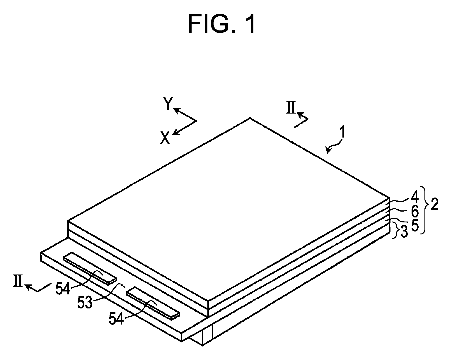
[0104]First, a liquid crystal display device and a liquid crystal display panel according to one embodiment of the present invention are described with reference to FIGS. 1 to 4.

[0105]A liquid crystal display device 1 shown in FIG. 1 includes a liquid crystal display panel 2 and a back light 3.

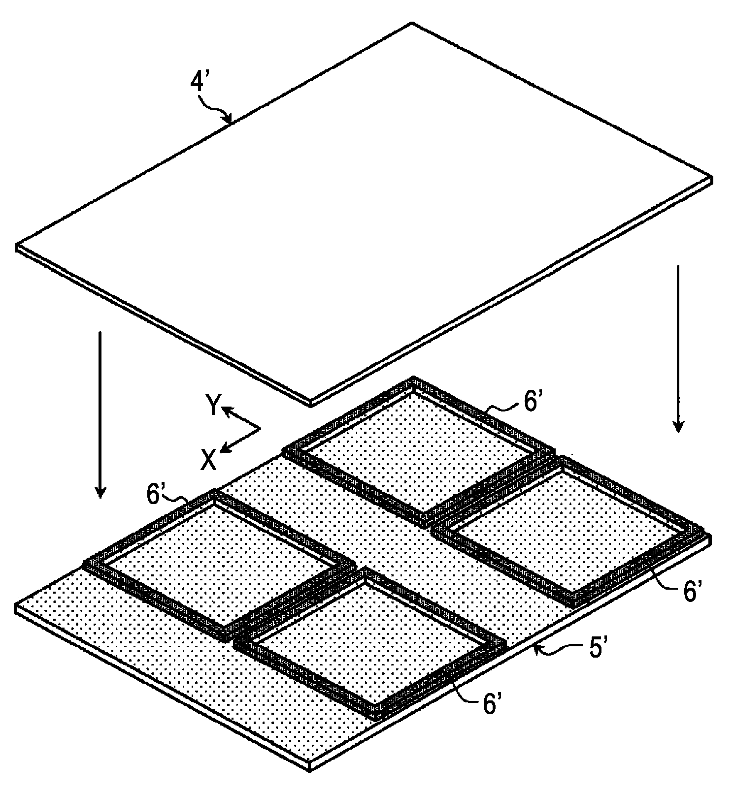
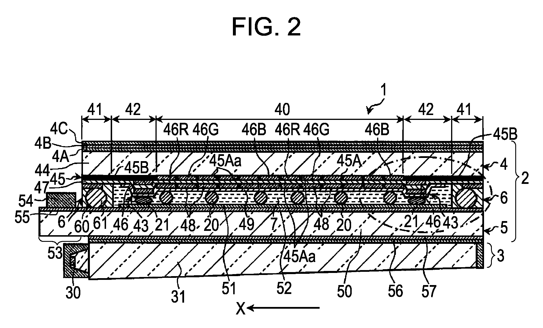
[0106]As shown in FIG. 2, the liquid crystal display panel 2 includes a first base 4, a second base 5, a plurality of spacers 20 and 21, a sealing member 6, and a liquid crystal layer 7.

[0107]As shown in FIGS. 2 to 4, the first base 4 includes a convex portion 43 having a frame shape in a peripheral region 42, which is a region between a display region 40 and a sealing region 41 sealed by the sealing member 6, to enclose the display region 40 with the convex portion 43. The convex portion 43 reduces the depth of the depression in the peripheral region 42, and reduces the depth of the ...


PUM


Abstract

The invention relates to a liquid crystal display panel 2 including a first base having a light shielding film 45, color filters 46R, 46G, 46B, 46, and a first display electrode 48 on a first transparent substrate 4; a second base 5 having a second display electrode 51 on a second transparent substrate 50, spacers 20 and 21 for keeping a distance between the first and the second bases 4 and 5; and a sealing member 6 for sealing a liquid crystal between the first and the second bases 4 and 5. At least one of the first and the second bases 4 and 5 includes a convex portion 43 between a display region 40 including display pixels and a sealing region 41 sealed by the sealing member 6, to enclose the display region 40 with the convex portion 43. The spacers 20 and 21 include a first spacer 20 in the display region 40 and a second spacer 21 on the convex portion.

Description

RELATED APPLICATIONS[0001]This application is the National Phase under 35 U.S.C. §371 of PCT International Application No. PCT / JP2006 / 319389 which has an International filing date of Sep. 28, 2006, which claims priority to Japanese Application No. 2005-283785 filed on Sep. 29, 2005. The entire contents of all applications listed above are hereby incorporated by reference.TECHNICAL FIELD[0002]The present invention relates to a color liquid crystal display panel having a color filter, a liquid crystal display device provided with the same, and a laminated substrate for liquid crystal display panels.BACKGROUND ART[0003]In recent years, liquid crystal display devices including liquid crystal display panels have been widely applied not only to relatively small information communication devices such as portable information terminals, but also to relatively large electric devices such as monitors and car navigation apparatuses. Such a liquid crystal display panel typically has a structure ...

Claims


Application Information

Patent Timeline
IPC IPC(8): G02F1/1335G02F1/1339
CPCG02F1/133351G02F1/13394G02F1/1339
Inventor SHIMIZU, TAKASHIMIYAZAKI, YOSHIOAOKI, KENGOUMOTOMURA, TOSHIROU
Owner KYOCERA CORP
Why Eureka
Try Eureka