Image output apparatus, projector, and method of controlling image output apparatus

a technology of image output and level adjustment amount, which is applied in the direction of instruments, television systems, static indicating devices, etc., can solve the problem of difficulty in accurately and achieve the effect of improving the accuracy of correcting the level adjustment amount and reducing display irregularities

Active Publication Date: 2009-11-26
SEIKO EPSON CORP
View PDF3 Cites 2 Cited by
  • Summary
  • Abstract
  • Description
  • Claims
  • Application Information

AI Technical Summary

Benefits of technology

[0008]An advantage of some aspects of the invention is that it improves the accuracy of correcting the level adjustment amount of each output circuit and sufficiently reducing display irregularity.

Problems solved by technology

As a result, the output of each of the output circuits varies due to the operation of the liquid crystal display, which makes it difficult to accurately correct the level adjustment amount.

Method used


Image

  • Image output apparatus, projector, and method of controlling image output apparatus
  • Image output apparatus, projector, and method of controlling image output apparatus
  • Image output apparatus, projector, and method of controlling image output apparatus

Examples


third modification

E3. Third Modification

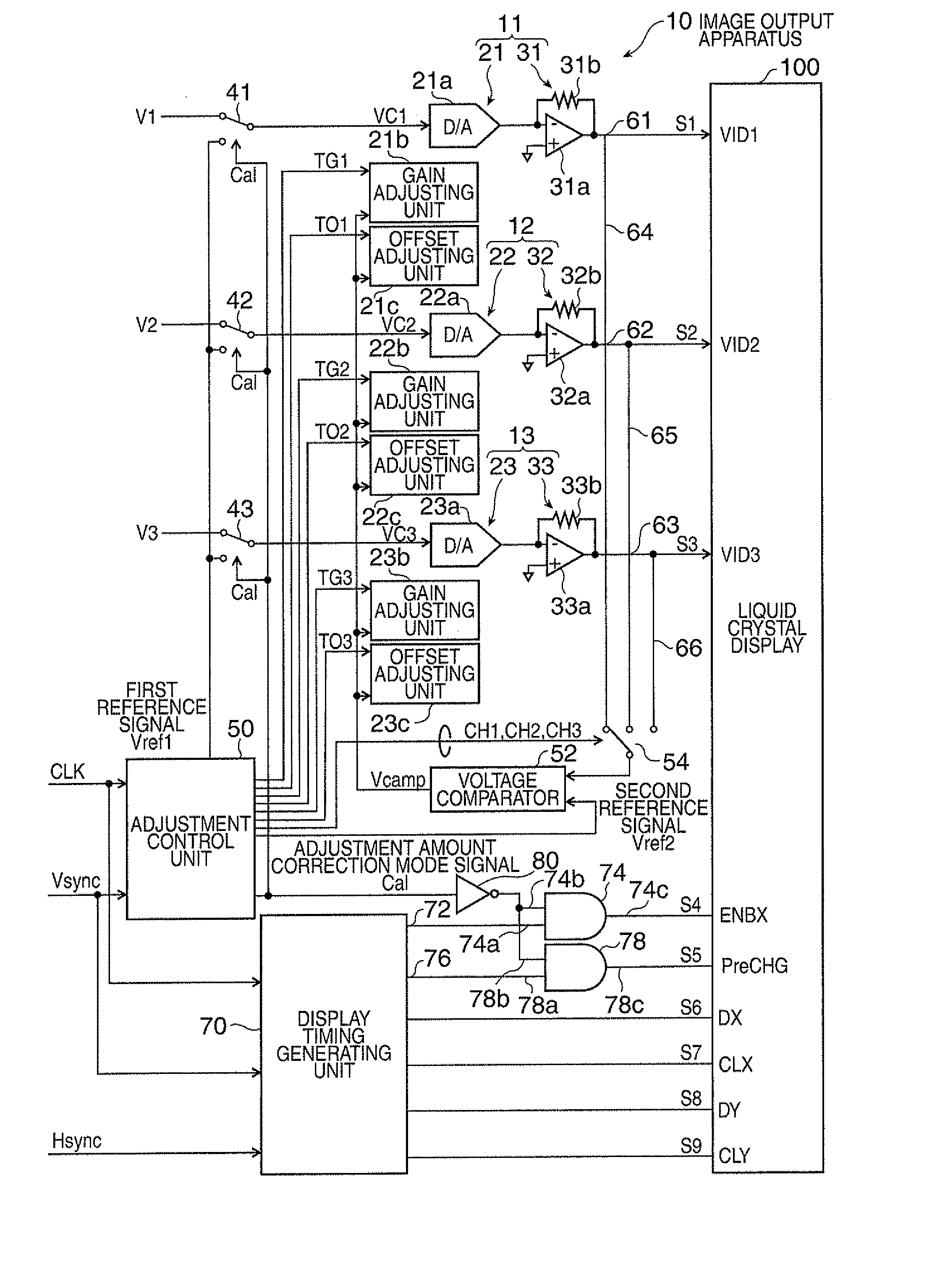
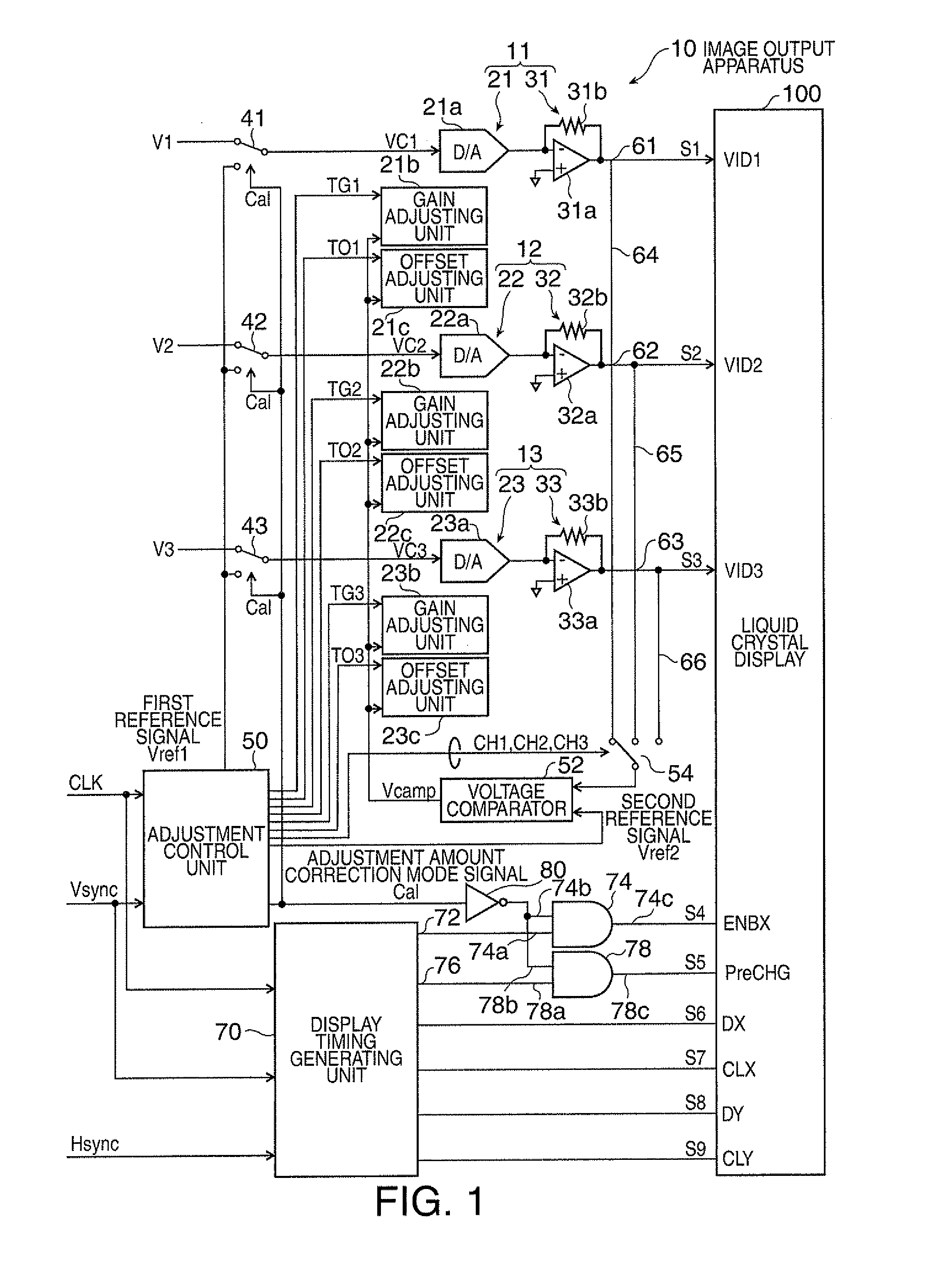
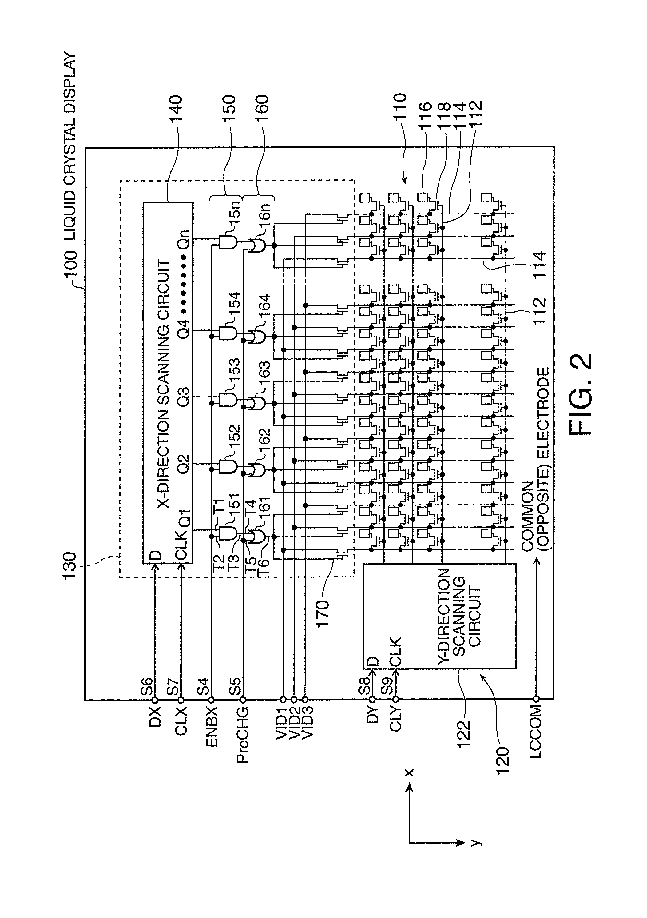
[0086]In the above-described embodiment, during the adjustment amount correction mode, the enable signal is changed to an inactive level, and the pre-charge timing signal is changed to an inactive level. However, in a structure in which the liquid crystal display device does not perform pre-charge, that is, in a structure in which the pre-charge timing signal terminal PreCHG and the OR circuits 161 to 16n are not provided, it is possible to turn off the scanning TFT 170 only by changing the enable signal to an inactive level. Therefore, during the adjustment amount correction mode, the image output apparatus may change only the enable signal to an inactive level. In addition, during the adjustment amount correction mode, the image output apparatus does not necessarily change the enable signal to the inactive level. The image output apparatus may change a control signal for turning off the scanning TFT 170 to an inactive level. Specifically, the image output app...

fourth modification

E4. Fourth Modification

[0087]In the above-described embodiment, the gains and offsets of the D / A converters 21a, 22a, and 23a are adjusted to correct the adjustment amount for adjusting the level of an input signal. However, only one of the gain and the offset may be adjusted. In addition, in the above-described embodiment, the output signal of each of the level adjusting units 11 to 13 when the first reference signal Vref1 is input is compared with the second reference signal Vref2, and the adjustment amounts of the corresponding level adjusting units 11 to 13 are increased or decreased by a predetermined correction amount such that the difference between the signals is reduced. However, after the comparison is performed, a correction amount may be changed on the basis of the difference between the signals, and the gain or offset may be increased or decreased by the correction amount. Further, the invention is not limited to the structure in which the adjustment amount of the D / A c...

fifth modification

E5. Fifth Modification

[0088]The above-described embodiment includes the image output apparatus 10 and the liquid crystal display 100. However, the invention may be applied to a projector. That is, the liquid crystal display 100 may be used as a liquid crystal panel, which is one of the parts of the projector, and the image output apparatus 10 may be provided in the projector.

[0089]In the above-described embodiment, a portion of the structure implemented by hardware may be replaced with software. Conversely, a portion of the structure implemented by software may be replaced with hardware.


PUM


Abstract

An image output apparatus includes: a display device having a light modulation section which is divided into a plurality of channels; a level adjusting unit that is provided to each of the channels adjusts a level of input signal, and outputs adjusted output signal to corresponding channel; a signal switching unit that switches between a video input signal and a first reference signal as the input signal of the level adjusting unit, for a predetermined period; an adjustment amount correcting unit that compares an output signal from each of the level adjusting units with a second reference signal for the predetermined period and corrects the adjustment amounts of the corresponding level adjusting units on the basis of the comparison results; and a connection state switching unit that outputs a control instruction to the display device to change a state of the channels to an open state for the predetermined period.

Description

[0001]The entire disclosure of Japanese Patent No. 2008-134623 filed May 22, 2008 is expressly incorporated by reference herein.BACKGROUND[0002]1. Technical Field[0003]The present invention relates to an image output apparatus, a projector including the image output apparatus, and a method of controlling the image output apparatus.[0004]2. Related Art[0005]For example, in a liquid crystal display, since there are a large number of pixels in a horizontal direction, a light modulation section filled with the pixels, is divided into a plurality of channels in the horizontal direction, and the divided channels are driven. In an image output apparatus connected to the liquid crystal display having the above-mentioned structure, it is necessary to make the output levels of output circuits provided for each channel equal to each other in order to prevent the occurrence of display irregularity.[0006]Therefore, JP-A-5-150751 discloses a structure that can adjust the levels of output circuits...

Claims


Application Information

Patent Timeline
Patent Type & Authority Applications(United States)
IPC IPC(8): H04N5/74
CPCG09G3/3688G09G2310/0248G09G2310/0297H04N9/312G09G2320/0242G09G2320/0693G09G2320/0233
Inventor SAGAWA, TAKAHIRO
Owner SEIKO EPSON CORP
Why Eureka
Try Eureka