Battery pack

Active Publication Date: 2010-06-17
PANASONIC EV ENERGY CO LTD
View PDF5 Cites 35 Cited by
  • Summary
  • Abstract
  • Description
  • Claims
  • Application Information

AI Technical Summary

Benefits of technology

[0015]According to various aspects of the present invention, because the heat generating unit is provided in the holding spacer itself, it is possible to reliably heat the battery module and prevent performance degradation under low temperature in a cold

Problems solved by technology

On the other hand, when the temperature is low, the output of the battery pack is reduced and sufficient performance cannot be achieved.
Although provision of the sheet-shaped heat generating structure which uniformly generates heat ov

Method used


Image

  • Battery pack
  • Battery pack
  • Battery pack

Examples


Example

[0027]A preferred embodiment of the present invention will now be described with reference to the drawings.

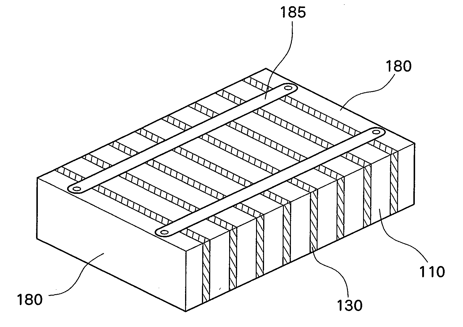
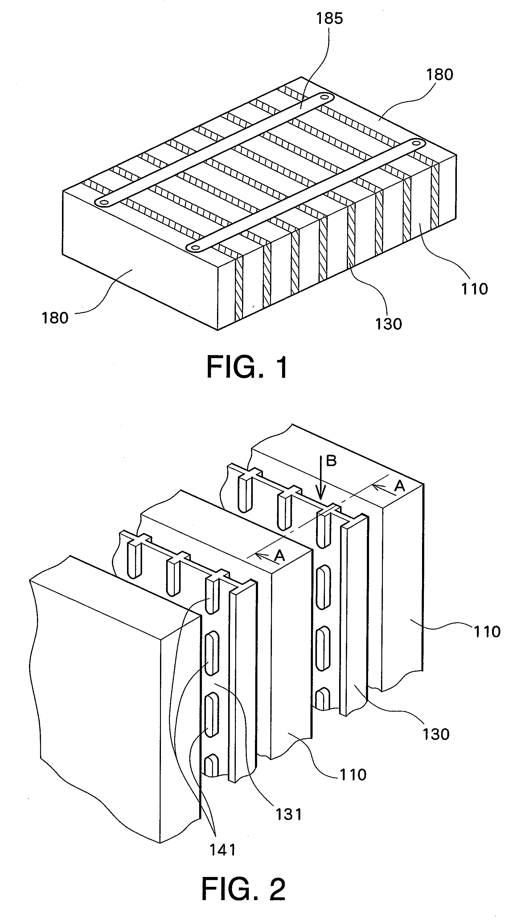
[0028]FIG. 1 shows a structure of a battery pack in a preferred embodiment of the present invention. The outer appearance shape is similar to that of the battery pack of the related art shown in FIG. 11, and a holding spacer 130 which holds battery modules 110 is placed between the battery modules 110. A cooling path through which a coolant is circulated is formed between the battery module 110 and the holding spacer 130. The battery module 110 and the holding spacer 130 are integrally restrained by two endplates (end boards) 180 and four restraining rods (or restraining bands) 185 to form an integrated structure. As shown in FIG. 10, each battery module 110 has an approximate rectangular parallelepiped shape with two opposing long side surfaces 110a and 110b, two opposing short side surfaces 110c and 110d, and two opposing end surfaces 110e and 110f. The battery module 110 com...


PUM


Abstract

A battery pack comprises a plurality of battery modules and a holding spacer which holds the battery module. A plurality of projections are provided on the holding spacer. The projections contact the battery module to hold the battery module and form a flow path for a coolant. A heat generating structure is embedded in the holding spacer or inserted into a hollow section of the holding spacer. In a cold climate, electricity is applied to the heat generating structure, to heat the battery module.

Description

PRIORITY INFORMATION[0001]This application claims priority to Japanese Patent Application No. 2008-320430, filed on Dec. 17, 2008, which is incorporated herein by reference in its entirety.BACKGROUND OF THE INVENTION[0002]1. Field of the Invention[0003]The present invention relates to a battery pack in which a plurality of battery modules each having a plurality of cells are stacked with a gap therebetween, and in particular, to a battery pack in which a spacer for holding a battery module is placed between adjacent battery modules.[0004]2. Description of the Related Art[0005]In the related art, there is known a battery pack wherein a plurality of battery modules each having a plurality of cells are placed, and a spacer is placed between adjacent battery modules. The battery pack is, for example, a secondary battery (such as a nickel-metal hydride battery or a lithium ion battery) which is used as a power supply of an electric vehicle and a hybrid electric vehicle.[0006]FIGS. 9-11 s...

Claims


Application Information

Patent Timeline
IPC IPC(8): H01M10/50H01M10/60H01M10/613H01M10/615H01M10/617H01M10/625H01M10/633H01M10/647H01M10/652H01M10/653H01M10/6554H01M10/6557H01M10/6571H01M50/204H01M50/262H01M50/289
CPCH01M2/1077H01M10/5004H01M10/5006H01M10/5083H01M10/5055H01M10/5059H01M10/5032H01M10/615H01M10/647H01M10/6571H01M10/6557H01M10/6555H01M10/613Y02E60/10H01M50/204H01M50/262H01M50/289
Inventor MARUKAWA, SHUHEINAKANISHI, TOSHIAKI
Owner PANASONIC EV ENERGY CO LTD
Why Eureka
Try Eureka