Image forming apparatus

Active Publication Date: 2015-12-10
CANON KK
View PDF7 Cites 1 Cited by
  • Summary
  • Abstract
  • Description
  • Claims
  • Application Information

AI Technical Summary

Benefits of technology

The invention allows for detection of a cartridge in an image forming apparatus without adding extra components. This helps to improve efficiency and accuracy in identifying the cartridge shape.

Problems solved by technology

In this case, a blank sheet might be output or, because of the lack of toner, friction between members will increase and a developer bearing member or the like might be damaged, thereby outputting a sheet on which vertical streaks are printed.
In the above example of the related art, however, a reading unit for a nonvolatile memory, a lever sensor, an optical sensor, or the like needs to be provided for the image forming apparatus, which undesirably increases the number of components and the cost.

Method used


Image

  • Image forming apparatus
  • Image forming apparatus
  • Image forming apparatus

Examples


first embodiment

[0023]A first embodiment of the present invention will be described.

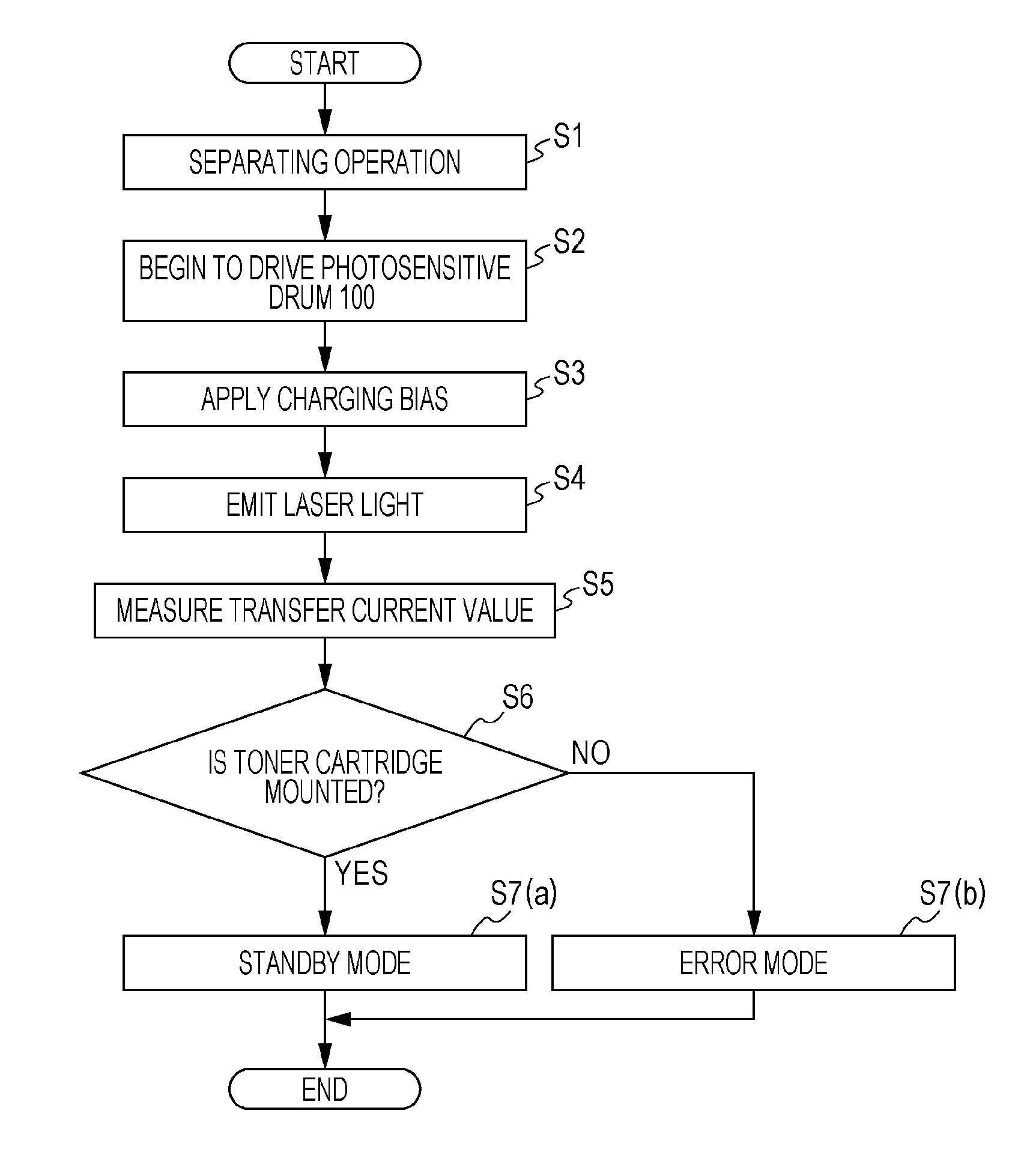
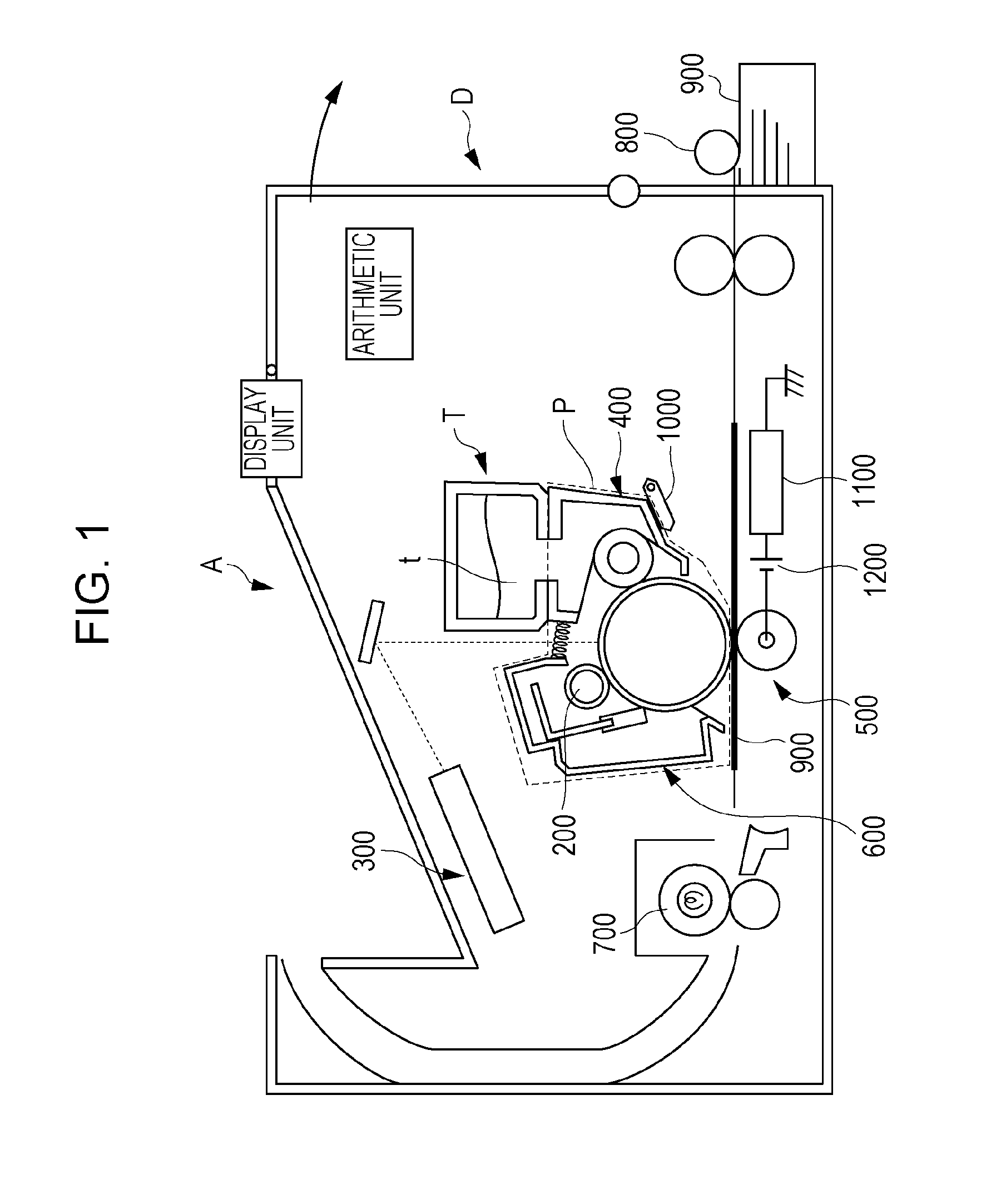
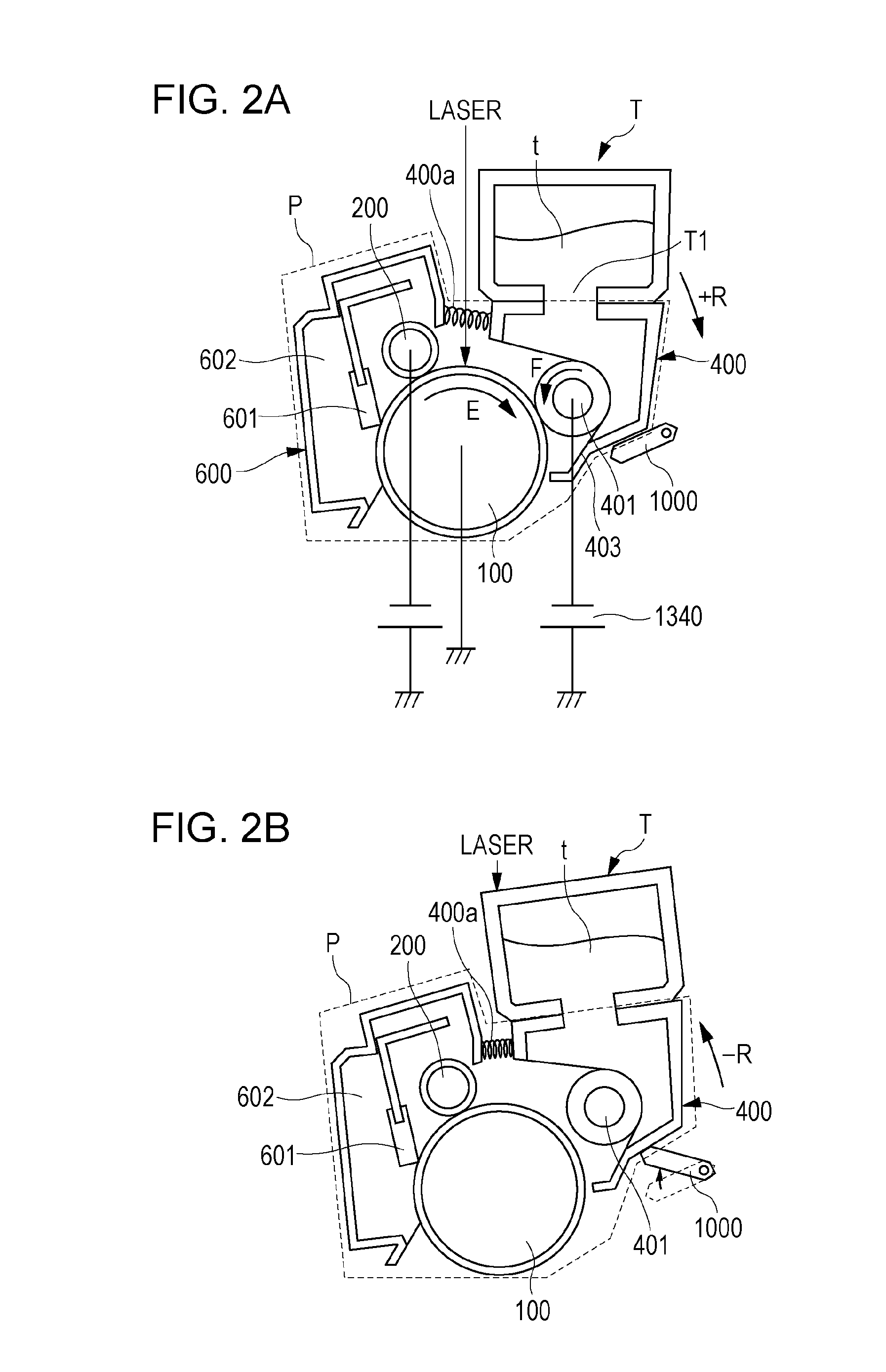
[0024]FIG. 1 is a schematic diagram illustrating an image forming apparatus A. FIGS. 2A and 2B are schematic diagrams illustrating a process cartridge P and a toner cartridge T according to the present embodiment.

[0025]The image forming apparatus A according to the present embodiment is an electrophotographic image forming apparatus that performs, on a photosensitive drum 100 as an image bearing member, a series of image forming processes including charging, emission of laser light, development, transfer, and cleaning to form an image on a recording material.

[0026]Here, the image forming apparatus A that performs the series of image forming processes includes the photosensitive drum 100 and a charging device (or a charging unit) including a charging roller 200 that uniformly charges a surface of the photosensitive drum 100. The image forming apparatus A also includes a light-emitting device 300 that emits laser ligh...

second embodiment

[0070]In a second embodiment, a type of toner cartridge mounted on an image forming apparatus on which one of toner cartridges of different sizes can be mounted is determined on the basis of a difference between shapes of the toner cartridges. In the present embodiment, a standard toner cartridge TA or a large-capacity toner cartridge TX may be mounted. A method for detecting presence or absence of a toner cartridge used in the present embodiment is the same as that used in the first embodiment, and accordingly redundant description thereof is omitted.

[0071]The large-capacity toner cartridge TX stores more toner t than the standard toner cartridge TA. By using the large-capacity toner cartridge TX, a user who prints images on a large number of sheets need not frequently replace the toner cartridge T, which increases usability.

[0072]If the development device 400 operates, unintentional spreading or cracking of the toner t might occur due to friction between a component of the develop...


PUM


Abstract

An image forming apparatus is provided that includes a light-emitting unit which emits light to an image bearing member which bears a developer image and that detects presence or absence of a developer container storing developer or a shape of the developer container on the basis of the number of electrons discharged from or received by the image bearing member when the light-emitting unit emits the light.

Description

BACKGROUND OF THE INVENTION[0001]1. Field of the Invention[0002]The present invention relates to an electrophotographic image forming apparatus such as a copying machine and a printer. The electrophotographic image forming apparatus (hereinafter referred to as an “image forming apparatus”) forms an image on a recording material, such as a sheet of paper, using an electrophotographic image forming method. The image forming apparatus may be, for example, a copying machine, a printer (a laser beam printer, a light-emitting diode (LED) printer, or the like), a facsimile apparatus, a word processor, or the like.[0003]2. Description of the Related Art[0004]First, by selectively emitting light to a photosensitive drum, which is an image bearing member uniformly charged by a charging device such as a charging roller, an image forming apparatus forms an electrostatic latent image on the photosensitive drum. The image forming apparatus then develops the electrostatic latent image to obtain a ...

Claims


Application Information

Patent Timeline
IPC IPC(8): G03G15/00
CPCG03G15/55G03G15/1645G03G15/5037G03G21/1875G03G2215/1614
Inventor TAMAGAKI, KUNIAKIADACHI, MOTOKISUNAHARA, SATOSHIWATANABE, TAKANORI
Owner CANON KK
Why Eureka
Try Eureka