Dental impression tray

a technology for dental impressions and trays, applied in the field of dental impression trays, can solve the problems of inconvenient patient, loss of dental impression accuracy, and difficulty in tooth removal, and achieve the effect of improving the retention of impression materials

Inactive Publication Date: 2010-06-17
3M INNOVATIVE PROPERTIES CO
View PDF9 Cites 14 Cited by
  • Summary
  • Abstract
  • Description
  • Claims
  • Application Information

AI Technical Summary

Benefits of technology

[0059]The dental impression tray according to the invention can preferably be molded in one step with the advantage that at the same time a retaining function for the dental impression material is provided, as opposed to having to provide an adhesive or other retaining system separately. Furthermore, the user of the tray, for example the dentist's assistant, does not have to prepare the dental tray to make it usable, for example by coating the inside of the reservoir with an adhesive. However, it would still be possible to use an adhesive together with the tray of the present invention to improve the retention of the impression material in the tray. With respect to recycling of a used tray it is also an advantage that a single material can be used for making the tray.
[0060]A further advantage may be provided by the fact that air can escape through the passageway when the impression material flows toward and around the retaining elements, and therefore the solidified impression material can link tightly with the retaining elements without most of the air bubbles that might otherwise be present. It is also a preferred advantage that the impression material flows under the retaining elements before it reaches the passageways, because impression material coming through the passageways indicates to the dentist that the impression material will be adequately retained in the tray. Furthermore, because the passageways provide a bottleneck for the flow of the impression material when the tray is placed on a patient's teeth, pressure is created that forces the material to flow around and near the retaining elements.

Problems solved by technology

Because the impression material flows around the teeth and then solidifies, it can be difficult to remove from the teeth even when significant force is applied to the tray.
In some cases, the force applied to the tray separates the impression material from the tray rather than from the teeth, which means that the impression material must be separately peeled away from the teeth, and the accuracy required for dental impressions gets lost.
This is inconvenient for the patient and the dentist because it tends to render the impression unusable, and as a result the procedure must be done again.
Generally it takes some effort to manufacture dental trays with integrated retaining elements, because several manufacturing steps are often necessary.

Method used


Image

  • Dental impression tray
  • Dental impression tray
  • Dental impression tray

Examples


Embodiment Construction

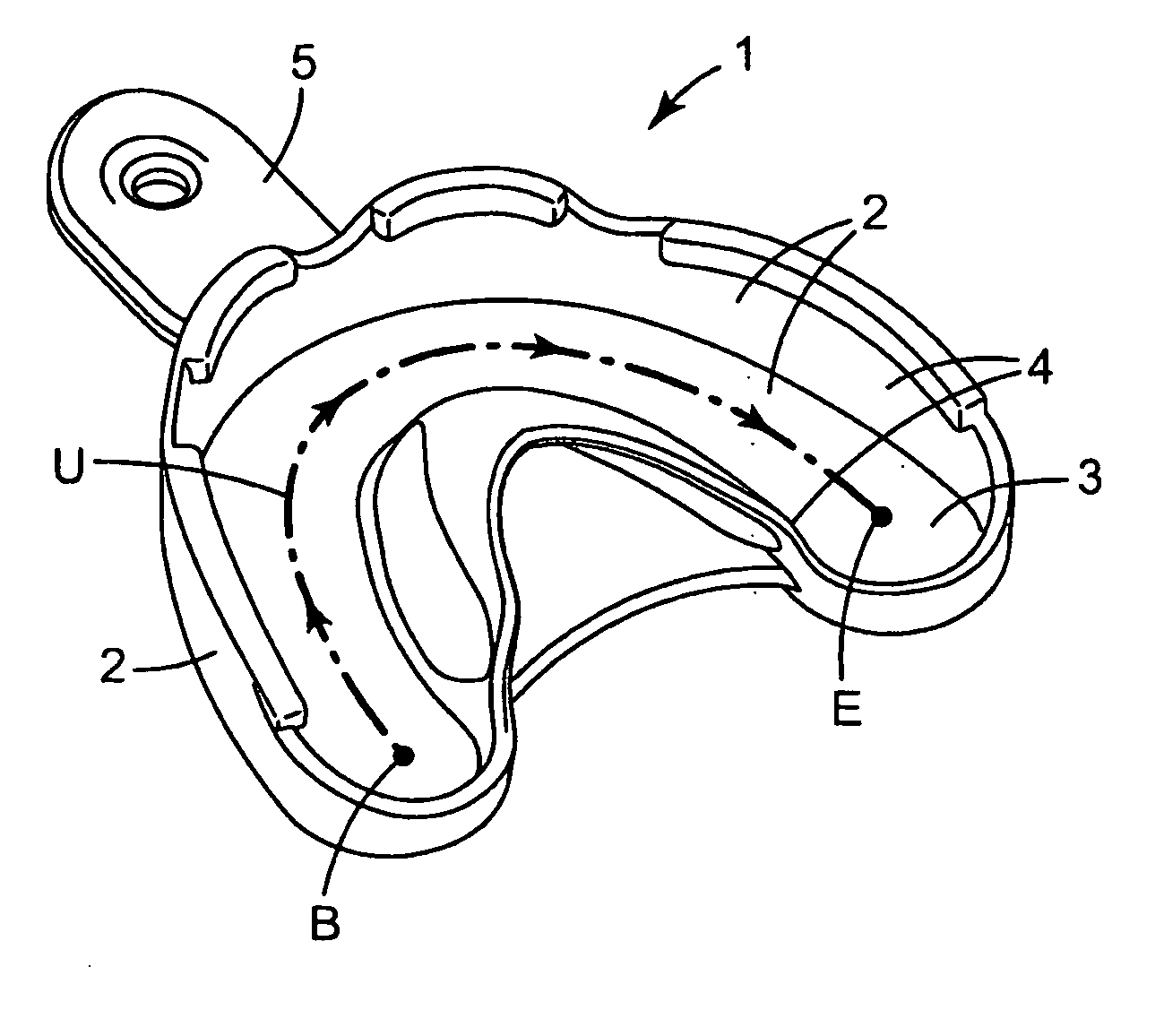
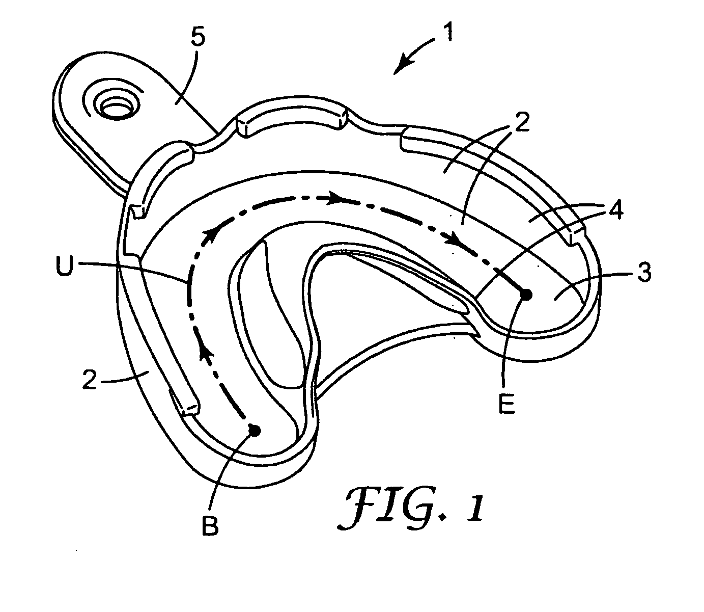
[0080]FIG. 1 shows the general structure of the dental impression tray 1. For clarity the retaining elements and passageways of the invention are not shown in this view, but different embodiments thereof are explained in detail below. The tray has at least one wall 2, which is typically a bottom wall 3 and tray side walls 4. The tray wall 2 forms a trough-shaped reservoir for receiving dental impression material. The reservoir extends in a U-shape as designated as “U” in FIG. 1. The tray may further comprise a grip 5 by which the tray can be held when used.

[0081]To prepare the tray, dental impression material is dispensed into the reservoir, for example, by use of a motorized Pentamix™ 2 dispensing device (not shown) available from 3M ESPE AG, Germany. The tray can also be filled by a syringe or other manually-operated dispensing apparatus. A user, for example a dentist or a dentist's assistant, usually fills the tray by continuously dispensing a pasty impression material into the r...


PUM


Abstract

A dental impression tray is provided having a wall comprising at least one retaining element. The retaining element at least partially overhangs an associated passageway, wherein the passageway extends between first and second wall surfaces that face in different directions. Further, methods and molds to form a dental impression tray according to the invention are provided and a kit comprising a plurality of such dental impression trays.

Description

FIELD OF THE INVENTION[0001]The present invention relates generally to dental impression trays and, more specifically, to dental impression trays having retaining elements for retaining a dental impression material within such trays. Furthermore the invention is related to methods and molds for manufacturing a dental tray according to the invention and a kit comprising such a tray.BACKGROUND OF THE INVENTION[0002]Dental impression trays are used to create negative reproductions of a patient's teeth. These reproductions are generally used to cast models, for example, as is often required for making dental restorations such as crowns and bridges. To take an impression, the dental impression tray is usually filled with a flowable impression material, and then the tray is placed in the patient's mouth and pressed against the teeth. The impression material solidifies while the tray remains in the patient's mouth. As soon as the impression material has become solid, the tray is peeled awa...

Claims


Application Information

Patent Timeline
Patent Type & Authority Applications(United States)
IPC IPC(8): A61C9/00
CPCA61C9/0006
Inventor GRAMANN, JENSOPPOLZER, ROBERTWAGNER, INGO W.MAHNEL, URS
Owner 3M INNOVATIVE PROPERTIES CO
Why Eureka
Try Eureka