
Percutaneous catheter directed intravascular occlusion devices

a technology of intravascular occlusion and percutaneous catheter, which is applied in the field of intravascular occlusion devices, can solve the problems of insufficient retention force, gaps between disk portions and vessel walls, and prior art devices that do not align themselves as well as possible to the anatomical conditions, etc., and achieves small transition diameter, easy flexibility, and improved flexibility.

Active Publication Date: 2011-10-11
ST JUDE MEDICAL CARDILOGY DIV INC
View PDF45 Cites 142 Cited by
  • Summary
  • Abstract
  • Description
  • Claims
  • Application Information

AI Technical Summary

Benefits of technology

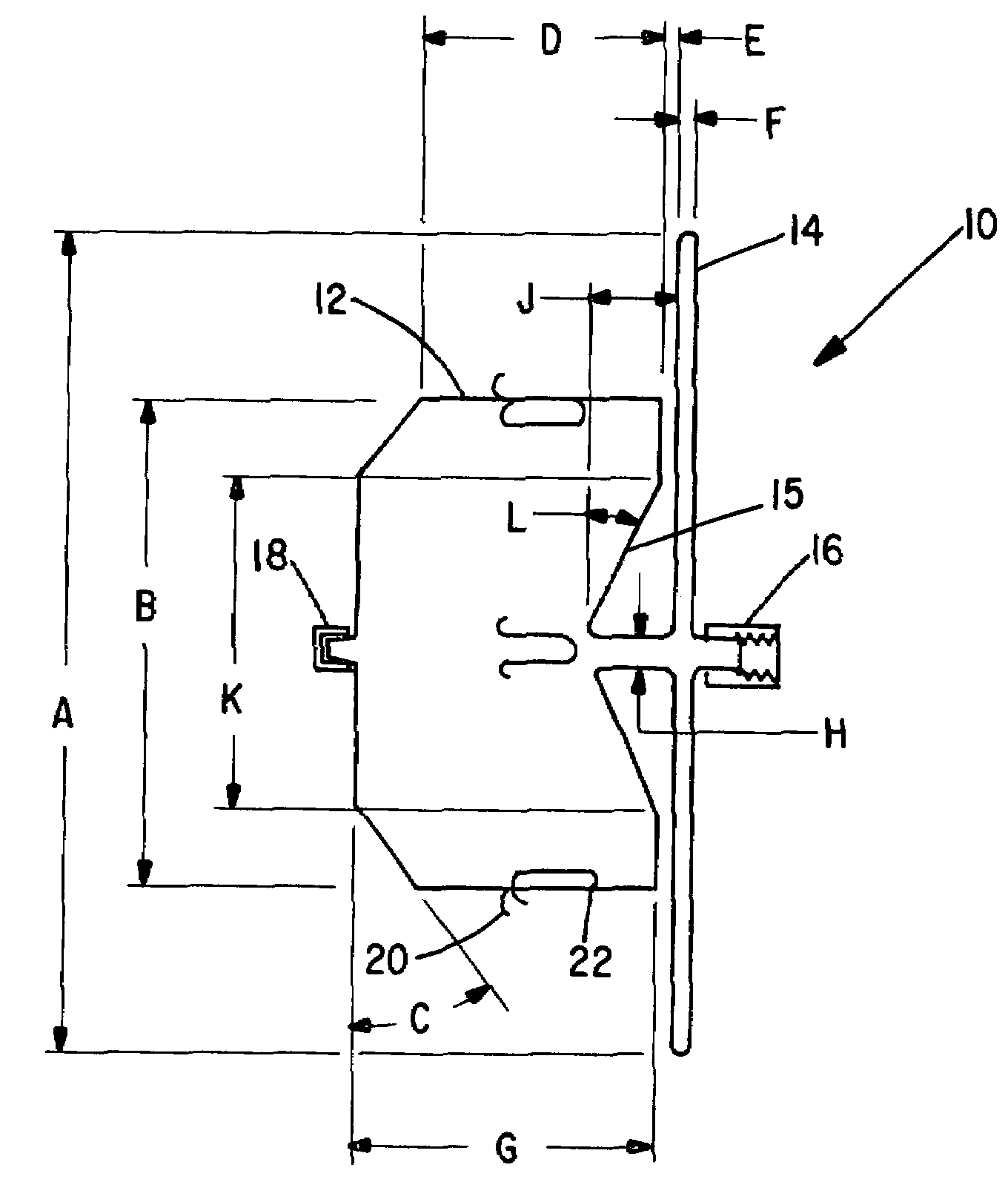
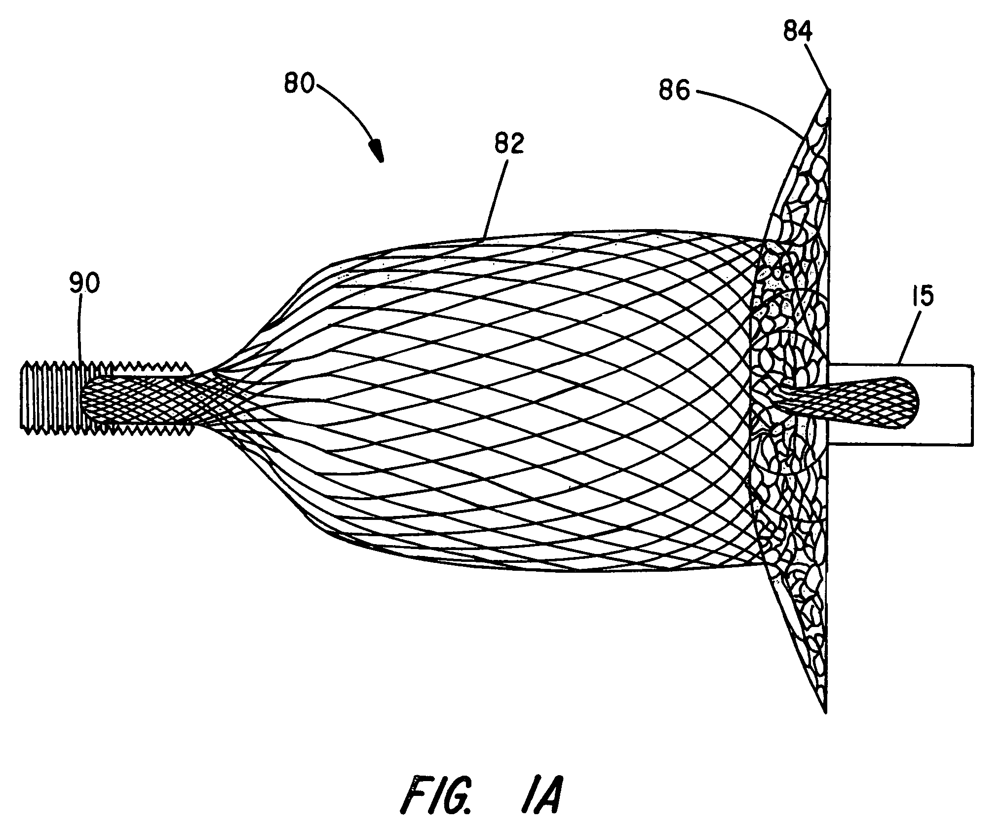
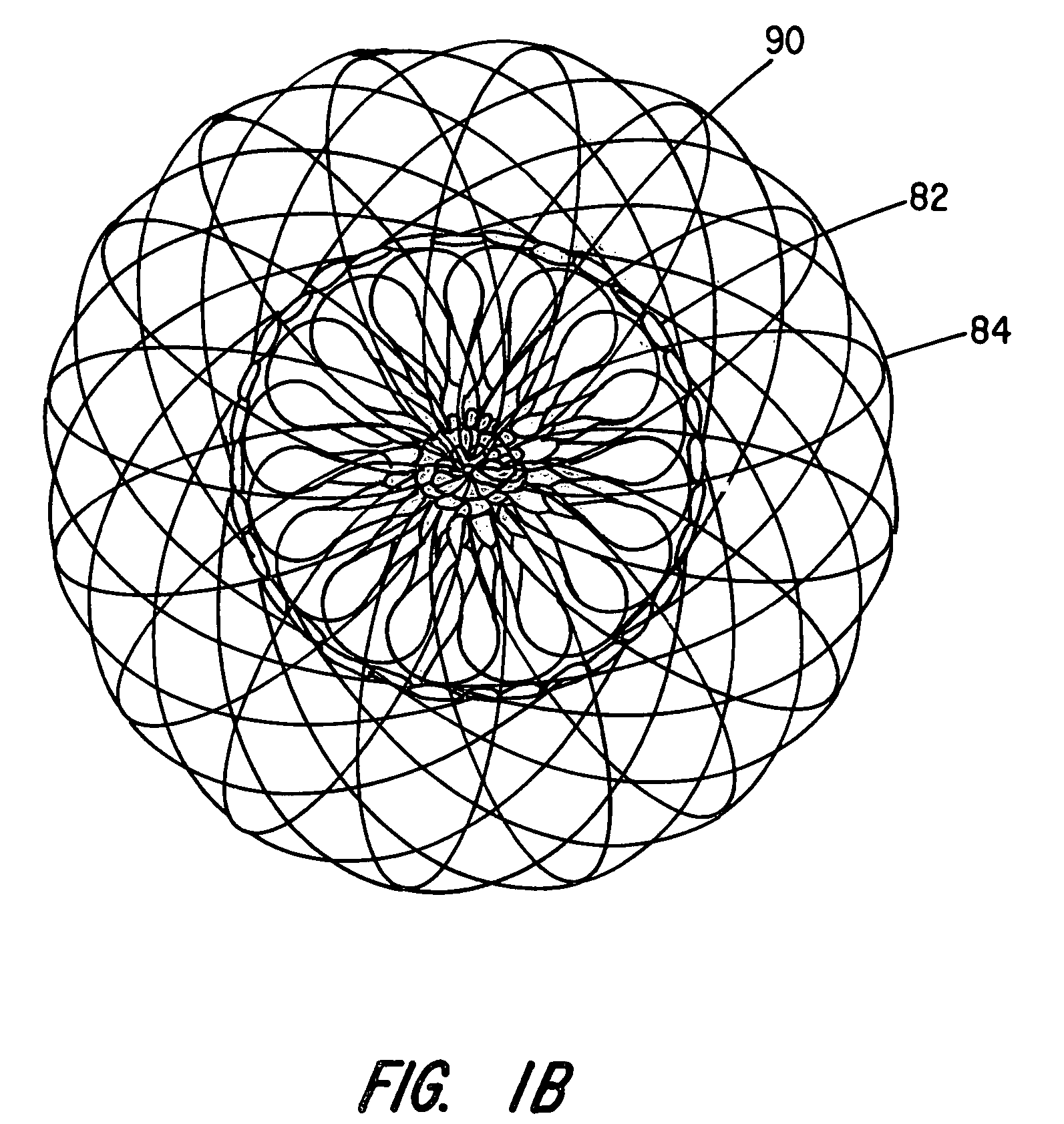
[0013]The inventive device improves the flexibility between the disk portion and the cylindrical middle portion by providing a very small transition diameter between the disk portion and middle portion, the transition diameter being much smaller than the middle portion diameter. This small transition diameter allows the disk to easily flex about this diameter to orient itself to the wall of the vessel containing the aperture to accommodate a wide range of anatomical variations between the axis of the lumen to be occluded and the wall containing the aperture to the lumen.
[0014]By recessing the portion having the small transition diameter within an indentation formed in the end of the cylindrical middle portion of the device, exact positioning of the device within a vessel is not overly critical. The recess allows the disk and cylindrical portion to remain in close proximity as they are in free space or will also allow the disk and cylindrical portion to separate a small distance while still maintaining device function.
[0015]The improved single disk device also has improved retention when compared to the prior art by the addition of flexible Nitinol shape memory wires sutured or fastened to or a part of the braided structure middle portion. The wires have a resilient hook end, designed to extend outward from the device middle portion surface, upon deployment, to reversibly engage the vessel wall to resist motion of the device toward the disk end. The hook end has no barb and allows the device to be repositioned by device movement opposite in direction (away from disk) to the pointed end of the hook. The device may also be withdrawn back into the delivery catheter after deployment by resiliently un-bending the hook as it is drawn back into the distal end of the catheter. The hook shaped wires add additional device retention to that provided by the sizing of the middle portion diameter larger than the vessel to be occluded.

Problems solved by technology

The mentioned prior art devices do not always align themselves as well as possible to the anatomical conditions due to the lack of bending flexibility between the cylindrical portion and the disk portion.
When this occurs, with the prior art devices, the disk attempts to align, but it's lack of flexibility causes portions of the disk to extend further from the vessel wall than desired which may interfere with blood flow or cause gaps between portions of the disk and the vessel wall.
Due to lack of precision in estimating the diameter of the vessel to be occluded or the body's ability to yield or dilate in response to pressure changes, and movement of the body, the retention force can occasionally be insufficient to retain the device in place as desired.

Method used


Image

  • Percutaneous catheter directed intravascular occlusion devices
  • Percutaneous catheter directed intravascular occlusion devices
  • Percutaneous catheter directed intravascular occlusion devices

Examples


Embodiment Construction

[0029]The present invention provides an improved percutaneous catheter directed intravascular occlusion device for use in the vasculature in patients' bodies, such as blood vessels, channels, lumens, a hole through tissue, cavities and the like. In forming a medical device of the invention, a metal fabric is formed of a plurality of wire strands having a predetermined relative orientation between the strands.

[0030]The metal strands define two sets of essentially parallel generally helical strands, with the strands of one set having a “hand”, i.e. a direction of rotation, opposite that of the other set. This defines a generally tubular fabric, known in the fabric industry as a tubular braid. The Amplatz and Kotula patents previously discussed describe medical devices and the methods of fabrication of such devices in great detail and detailed further discussion is not needed.

[0031]The pitch of the wire strands (i.e. the angle defined between the turns of the wire and the axis of the b...


PUM


Abstract

The present invention provides an improved vascular occlusion device having improved flexibility and retention of the type fabricated from braided tubular metal fabric having an expanded preset configuration and an elongated collapsed reduced diameter configuration for delivery through a catheter to a treatment site and shaped to create an occlusion of an abnormal opening in a body organ or vessel, the woven metal fabric having a memory property whereby the medical device tends to return to said expanded preset configuration when unconstrained. The device further including at least one disk portion adjacent a body cylindrical portion formed from the fabric and having a transition diameter between the disk and cylindrical portion, significantly smaller than the diameter of the disk and the diameter of the cylindrical portion.

Description

BACKGROUND OF THE INVENTION[0001]I. Field of the Invention[0002]The present invention generally relates to intravascular devices for treating certain medical conditions and, more particularly, relates to intravascular occlusion devices for selective occlusion of a vessel anywhere in the body's circulatory system where it is desired to stop the flow of blood. The devices made in accordance with the invention are particularly well suited for delivery through a catheter or the like to a remote location in a patient's vascular system within a patient's body whereby a passageway to be occluded, has an axis and at least one aperture which intersects another vessel wall somewhat perpendicular to the axis.[0003]II. Description of the Related Art[0004]A wide variety of intravascular devices are used in various medical procedures. Certain intravascular devices, such as catheters and guidewires, are generally used simply to deliver fluids or other medical devices to specific locations within a...

Claims


Application Information

Patent Timeline
Patent Type & Authority Patents(United States)
IPC IPC(8): A61B17/08A61F2/06
CPCA61B17/0057A61B17/12022A61B17/12109A61B17/12122A61B17/12172A61B17/12177A61B2017/00867A61B2017/00575A61B2017/00592A61B2017/00606A61B2017/00628A61B2017/00632A61B17/00A61F2/00A61M25/01A61B17/08
Inventor AMPLATZ, KURTGU, XIAOPINGOSLUND, JOHN C.
Owner ST JUDE MEDICAL CARDILOGY DIV INC
Learn More