Spinal fixation assembly

Inactive Publication Date: 2010-06-17
INGENIUM
View PDF48 Cites 248 Cited by
  • Summary
  • Abstract
  • Description
  • Claims
  • Application Information

AI Technical Summary

Benefits of technology

[0014]Features that are described and / or illustrated with respect to one embodiment may be used in the same way or in a similar way in one or more other embodiments and / or in combination with or instead of the features of the other embodiments.

Problems solved by technology

One of the main challenges associated with internal spinal fixation is securing the fixation device to the spine without damaging the spinal cord.

Method used


Image

  • Spinal fixation assembly
  • Spinal fixation assembly
  • Spinal fixation assembly

Examples


Embodiment Construction

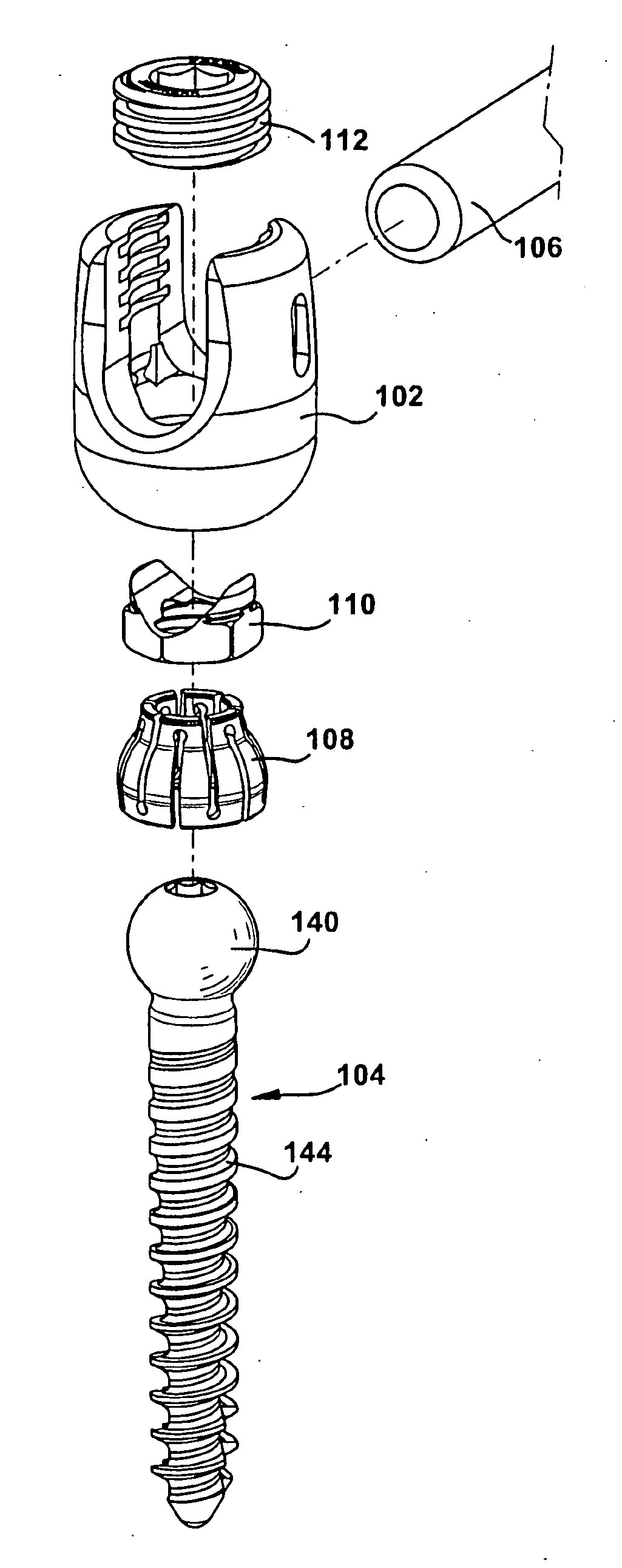
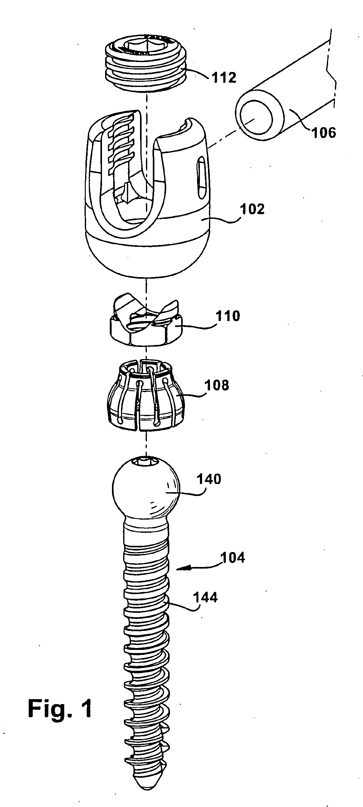
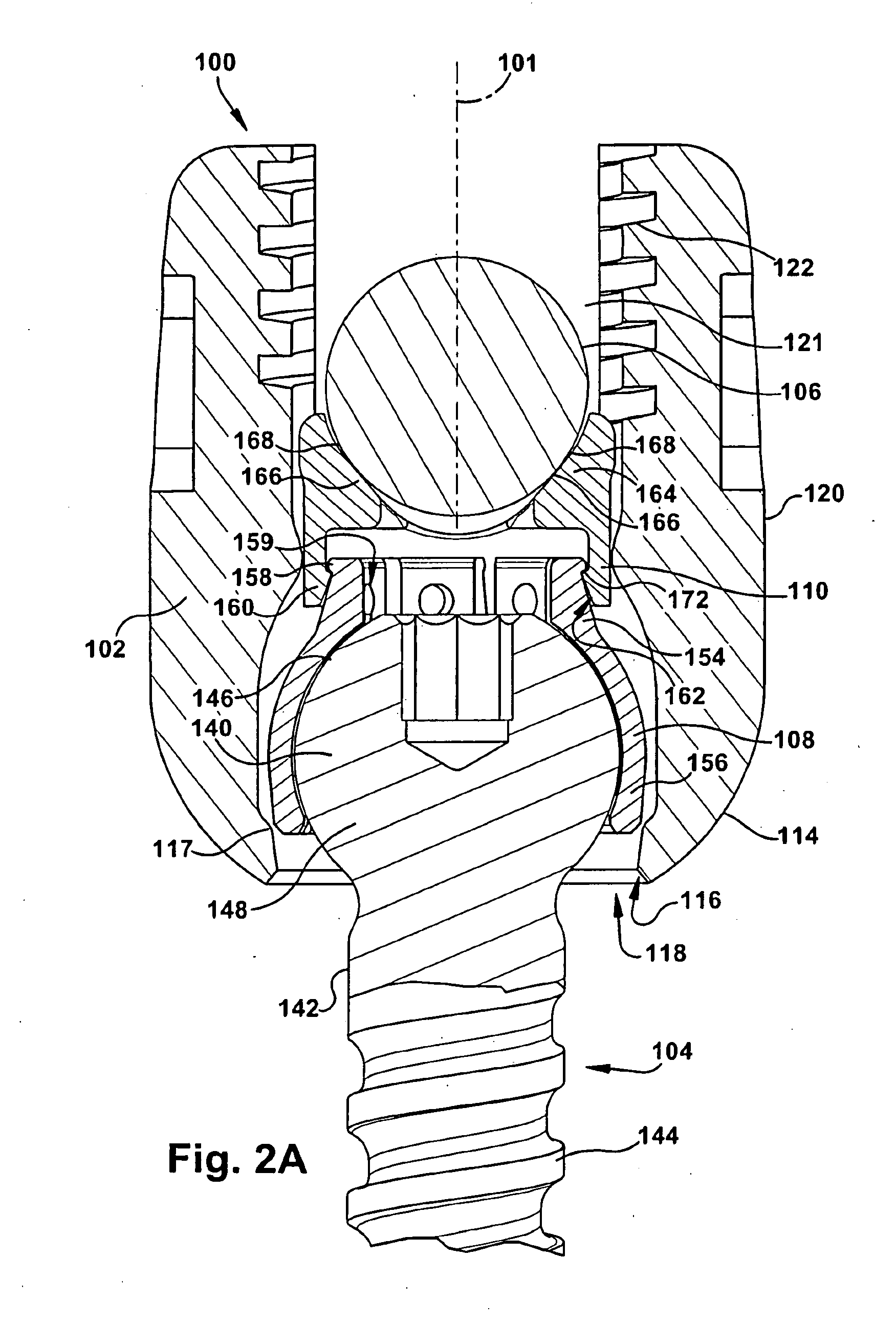
[0027]The invention relates to a novel locking mechanism and method for locking the relative positions of a rod and a fixation device. The locking mechanism provides an improved lock between a rod and the head of a fixation device, such as a screw. The apparatus includes a body and an internal insert that at least partially surrounds the head of the fixation device. When the locking mechanism is used to lock the fixation device, the insert preferably functions to “squeeze” the head of the fixation device so that forces are applied to both the upper and lower portions of the head, thereby fixing the fixation device with respect to the body. In addition, the insert may be configured to cause forces having both lateral and vertical components to be applied to the head of the fixation device to prevent its movement.

[0028]The invention may also include a novel rod seat that applies lateral forces to the insert when compressed into the insert as the rod is urged downward in the body. In a...


PUM


Abstract

A locking mechanism (100) and method of fixation, such as the fixation of a fixation device (104) like a bone screw and of a rod (106) to the spine. The locking mechanism (100) includes a body (102), an insert (108, 308), a rod seat (110, 310) and a set screw. The body (102) includes a bottom portion (114) configured to receive the fixation device (104) and the insert (108, 308) but prevents the insert (108, 308) and fixation device (104) from passing therethrough once the insert (108, 308) and fixation device (104) are engaged. The body (102) further includes a side portion (120) configured to receive the rod (106). Between the rod (106) and the insert (108, 308) is a rod seat (110, 310).

Description

FIELD OF THE INVENTION[0001]The present invention relates generally to prostheses for treating spinal pathologies, and more specifically to spinal fixation assemblies including an anchor for holding a fixation device and a stabilization rod.BACKGROUND OF THE INVENTION[0002]Various methods of spinal immobilization have been used in the treatment of spinal instability and displacement. The most common treatment for spinal stabilization is immobilization of the joint by surgical fusion, or arthrodesis. This has been known for almost a century. In many cases, however, pseudoarthrosis occurs, particularly in cases involving fusion across the lumbosacral articulation and when more than two vertebrae are fused together. Early in the century, post operative external immobilization, such as through the use of splints and casts, was the favored method of spinal fixation. As surgical techniques became more sophisticated, various new methods of internal and external fixation were developed.[000...

Claims


Application Information

Patent Timeline
Patent Type & Authority Applications(United States)
IPC IPC(8): A61B17/86
CPCA61B17/7002A61B17/7037A61B17/7032
Inventor WALSH, DAVID A.KNOBLOCH, CARL ARTHURBAKER, DANIEL R.
Owner INGENIUM
Why Eureka
Try Eureka