
Systems and methods for determining filter service lives

a technology of system and filter, applied in the direction of mechanical means, separation processes, instruments, etc., can solve the problems of shortening the service life of filters, increasing the risk of injury or illness, and the operator of the respirator may not safely inhale a contaminan

Active Publication Date: 2010-06-17
SCOTT TECH INC
View PDF25 Cites 86 Cited by
  • Summary
  • Abstract
  • Description
  • Claims
  • Application Information

AI Technical Summary

Benefits of technology

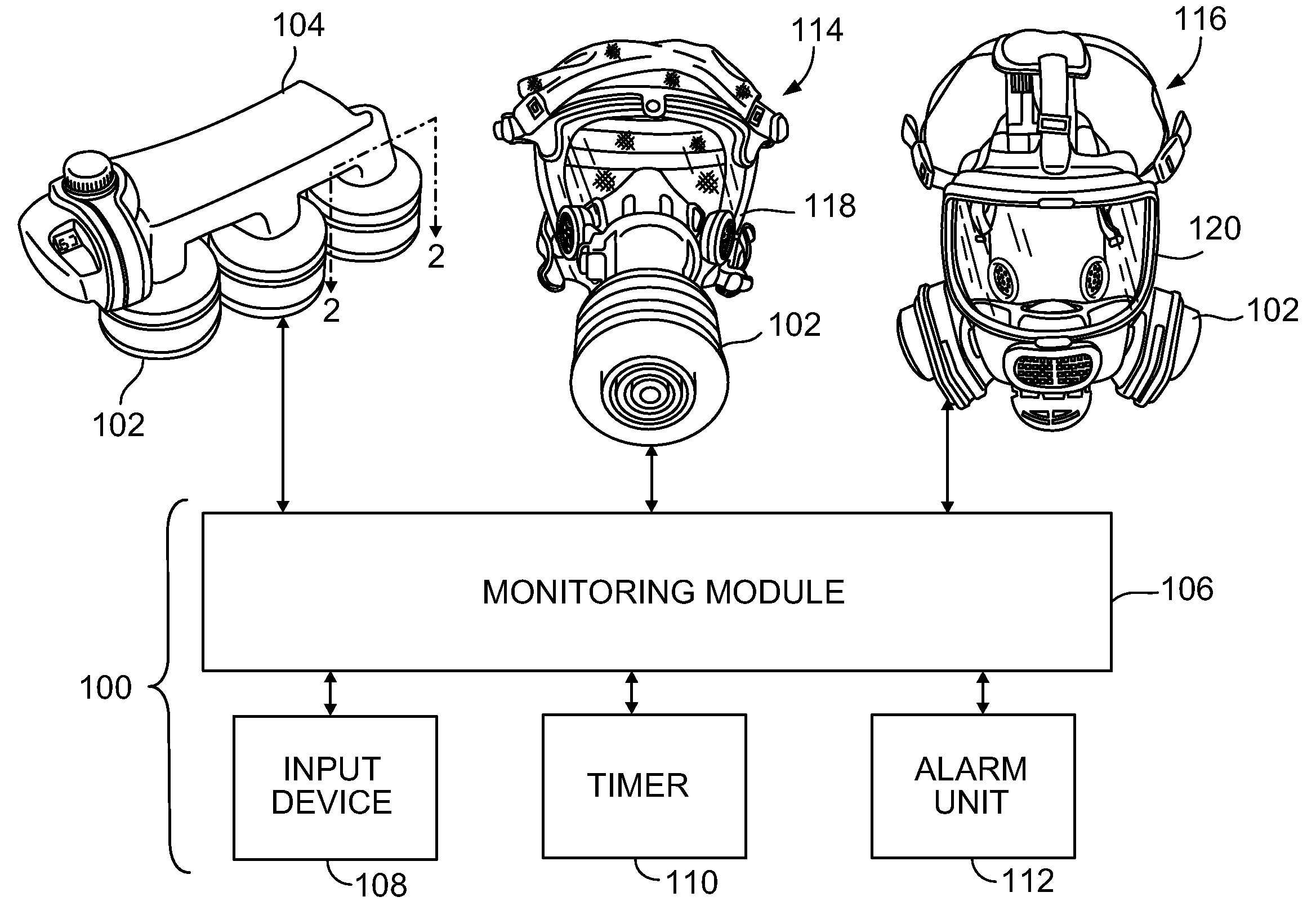
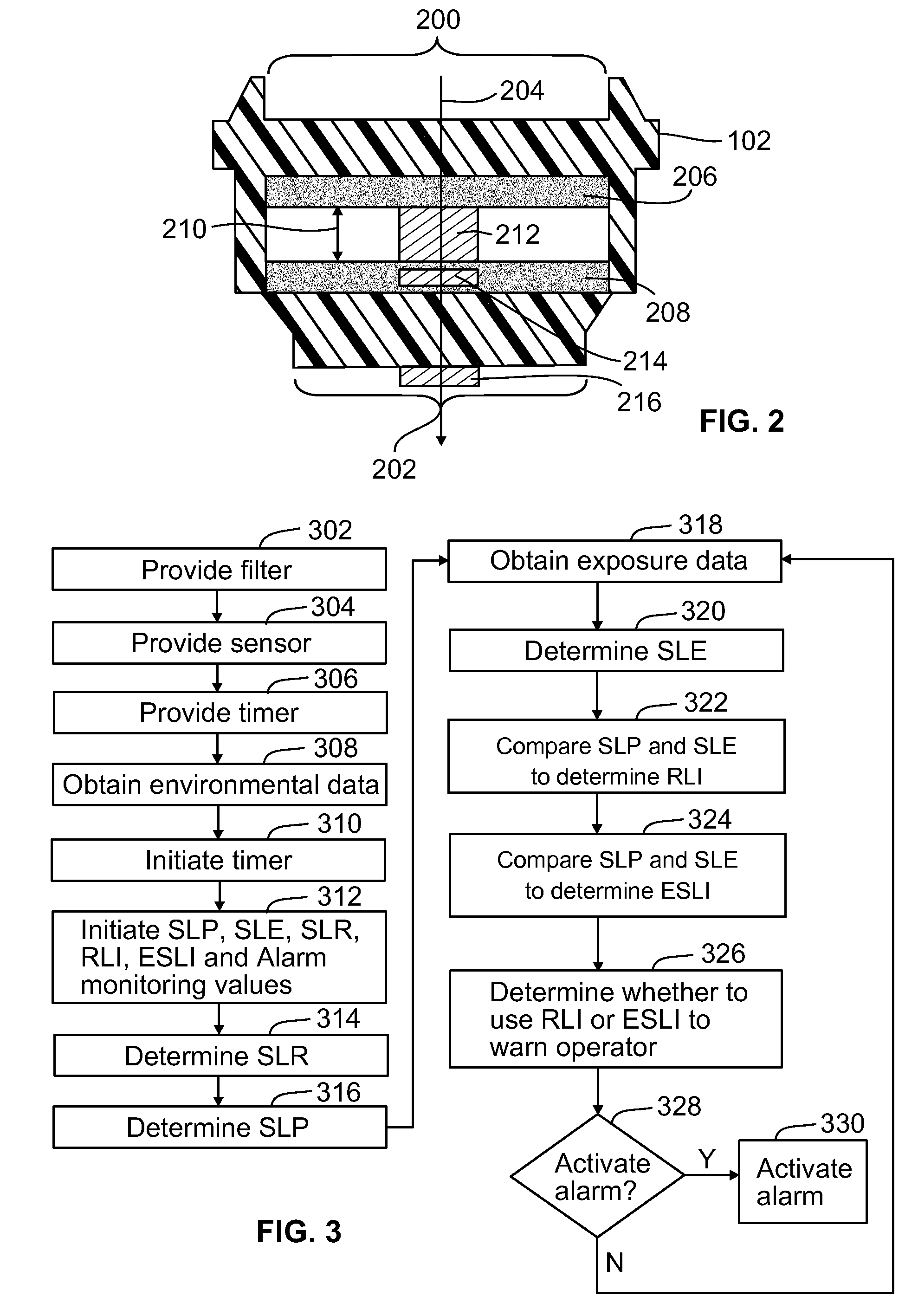
[0006]In one embodiment, a method for determining a service life for a filter is provided. The method includes measuring exposure data and calculating a service life estimate based on the exposure data. The service life estimate is representative of an estimated exposure time that the filter is exposed to ambient conditions represented by the exposure data before the contaminant passes through the filter at a breakthrough concentration. The method also includes obtaining environmental data and establishing a predicted service life based on the environmental data. The predicted service life is representative of a predicted exposure time that the filter is exposed to the ambient conditions represented by the environmental data before the contaminant passes through the filter at the breakthrough concentration. The method further includes determining the service life for the filter based on a comparison of the estimated and predicted service lives. Optionally, the service life may be representative of a time period that the filter prevents the contaminant from passing through the filter above the breakthrough concentration. The exposure data may be representative of one or more of the ambient conditions to which the filter is exposed. The environmental data may be representative of one or more of the ambient conditions and be obtained from an input that differs from the sensor.
[0007]In another embodiment, a computer-readable storage medium comprising one or more sets of instructions for determining a service life for a filter is provided. The instructions include instructions for receiving exposure data and environmental data and instructions for calculating a service life estimate based on the exposure data and a service life prediction based on the environmental data. The instructions also include instructions for determining the service life for the filter based on a comparison of the service life prediction and the service life estimate. Optionally, the instructions may also include instructions for calculating a residual life indicator based on the comparison of the service life prediction and the service life estimate, where the residual life indicator is representative of a remaining time period during which the filter is exposed to the ambient conditions before the chemical contaminant passes through the filter at the breakthrough concentration.

Problems solved by technology

For example, the operator of the respirator may not safely inhale a contaminant at concentrations above the breakthrough concentration without a significant increase in the risk of injury or illness from the contaminant.
For example, varying temperatures, barometric pressures, humidity, contaminant concentrations, breathing rates, chemical contaminants, and the like may significantly shorten the service lives of filters.
If the shortened service life of a filter is not accurately tracked or measured, the operator of the respirator faces an increased risk of harm by using a filter after the filter's service life has expired.
The service lives provided by the change out schedules are predetermined and may not account for changes to the service lives during use of the filters.
For example, the change out schedules may not dynamically adjust the expected service life of a filter when the filter is used in an environment where the ambient conditions may shorten the service lives of the filter during use of the filter.
But, these known ELSIs suffer from many drawbacks, including the inability to factor in a variety of environmental factors into the determination of the end of the filter service life.

Method used


Image

  • Systems and methods for determining filter service lives
  • Systems and methods for determining filter service lives
  • Systems and methods for determining filter service lives

Examples


Embodiment Construction

[0015]The foregoing summary, as well as the following detailed description of certain embodiments of the present invention, will be better understood when read in conjunction with the appended drawings. To the extent that the figures illustrate diagrams of the functional blocks of various embodiments, the functional blocks are not necessarily indicative of the division between hardware circuitry. Thus, for example, one or more of the functional blocks (for example, processors or memories) may be implemented in a single piece of hardware (for example, a general purpose signal processor or random access memory, hard disk, or the like). Similarly, the programs may be stand alone programs, may be incorporated as subroutines in an operating system, may be functions in an installed software package, and the like. It should be understood that the various embodiments are not limited to the arrangements and instrumentality shown in the drawings.

[0016]As used herein, an element or step recite...


PUM


Abstract

A method for determining a service life for a filter includes measuring exposure data and calculating a service life estimate based on the exposure data. The service life estimate is representative of an estimated exposure time that the filter is exposed to ambient conditions represented by the exposure data before the contaminant passes through the filter at a breakthrough concentration. The method also includes obtaining environmental data and establishing a predicted service life based on the environmental data. The predicted service life is representative of a predicted exposure time that the filter is exposed to the ambient conditions represented by the environmental data before the contaminant passes through the filter at the breakthrough concentration. The method further includes determining the service life for the filter based on a comparison of the estimated and predicted service lives.

Description

BACKGROUND OF THE INVENTION[0001]This invention relates generally to systems and methods for determining the service life of air filters, and more particularly, for a system and method for calculating the service lives of filters for air purifying respirators.[0002]Air purifying respirators (“APR”), including powered air purifying respirators (“PAPR”) rely on filters to remove chemical contaminants from the air flow through the respirator and into an operator's airway. Known filters prevent or impede the passage of one or more chemical contaminants from the atmosphere surrounding the respirator into the operator's airway through the filter. The filters may be used to filter the chemical contaminants for a limited time. For example, known filters prevent chemical contaminants from passing through the filters at concentrations above a breakthrough concentration for a service life of the filter. The breakthrough concentration may be an upper safety threshold for inhalation of the conta...

Claims


Application Information

Patent Timeline
Patent Type & Authority Applications(United States)
IPC IPC(8): G06F19/00
CPCA62B9/006A62B18/088B01D53/0415B01D2259/4541B01D2257/406B01D2257/602B01D2257/7027B01D2257/2064
Inventor PARHAM, MICHAELDING, YUQING
Owner SCOTT TECH INC
Learn More