Elevator Brake Condition Testing

a technology for elevators and brakes, applied in elevators, instruments, force/torque/work measurement apparatus, etc., can solve problems such as cumbersome process, brake failure to hold elevator in place on landing, and inability to easily verify brake capacity

Inactive Publication Date: 2010-06-24
OTIS ELEVATOR CO
View PDF7 Cites 44 Cited by
  • Summary
  • Abstract
  • Description
  • Claims
  • Application Information

AI Technical Summary

Problems solved by technology

Thus, the brake capacity is not easily verifiable through normal use, and wear of the brake linings, foreign particles in the brakes, and brake aging may cause the brake to fail to hold the elevator in place on a landing.
Howeve...

Method used


Image

  • Elevator Brake Condition Testing
  • Elevator Brake Condition Testing
  • Elevator Brake Condition Testing

Examples


Embodiment Construction

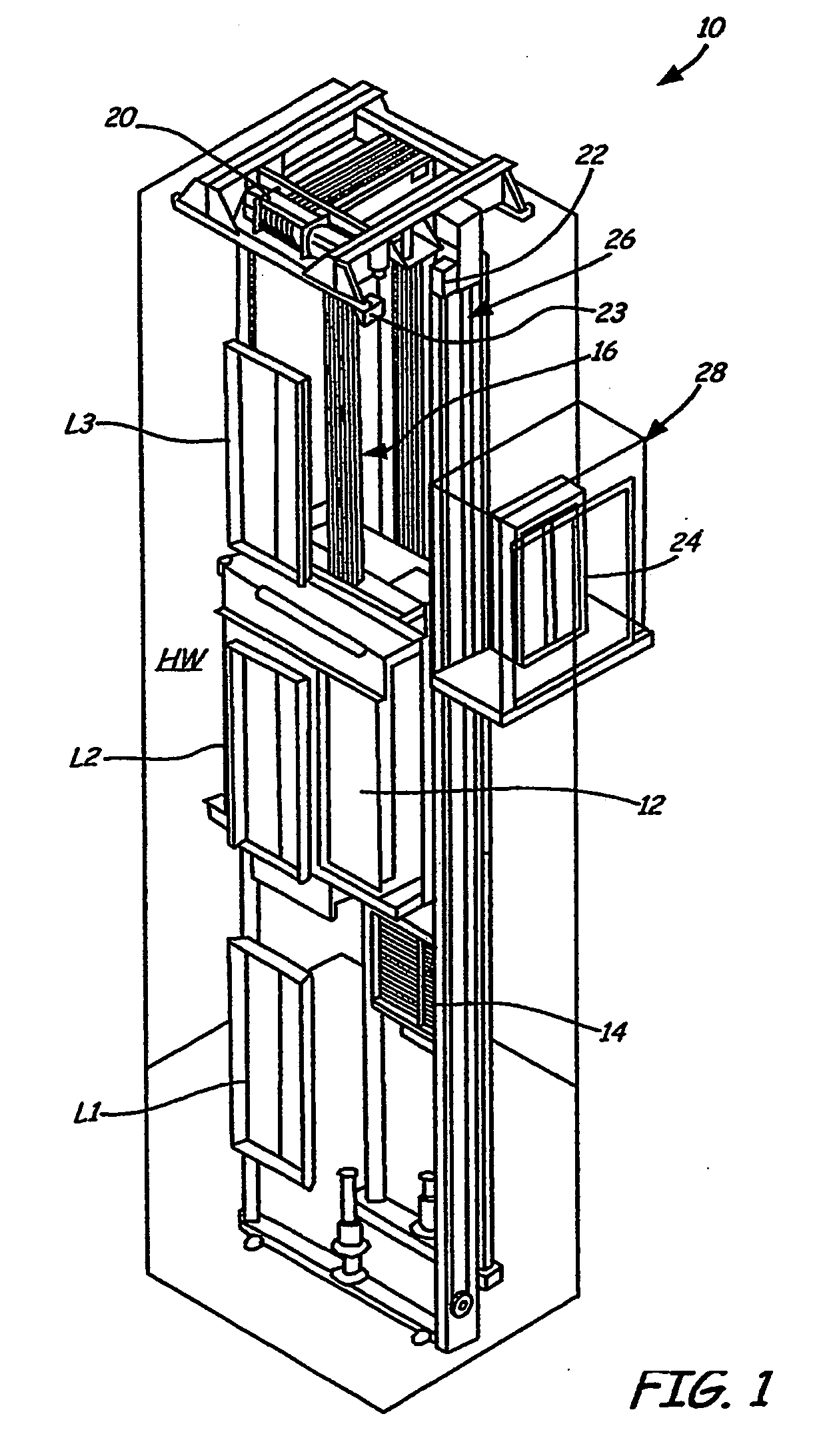
[0009]FIG. 1 is a perspective view of an elevator system 10 including elevator car 12, counterweight 14, ropes 16, elevator hoist machine 20, position encoder 22, limit switch 23, and controller 24. Elevator car 12 and counterweight 14 are connected with ropes 16 and suspended in hoistway HW including landings L1, L2, and L3.

[0010]Elevator car 12 and counterweight 14 are interconnected by ropes 16 to move concurrently and in opposite directions within hoistway HW. Counterweight 14 balances the load of elevator car 12 and facilitates movement of elevator car 12. In one embodiment, counterweight 14 has a mass approximately equal to the mass of elevator car 12 plus one half of the maximum rated load of elevator car 12. Ropes 16 may include steel cables or coated steel belts. Ropes 16 engage elevator hoist machine 20, which controls movement between elevator car 12 and counterweight 14.

[0011]Position encoder 22 is mounted on the upper sheave of elevator speed governor system 26. Positio...


PUM


Abstract

A brake (42) is tested in an elevator system (10) including a car (12) and a counterweight (14) connected to the car (12) by a rope (16). The car (12) is positioned at a reference position in the hoistway (HW) adjacent to a hoistway limit switch (23), and the brake (42) is engaged to hold the car (12) at the reference position. The rotating member (46) is then driven to provide a testing force on the brake (42) that simulates a load in the elevator car (12) of at least a maximum rated load for the car (12). The brake test is terminated if the hoistway limit switch (23) is actuated.

Description

BACKGROUND OF THE INVENTION[0001]The present invention relates to elevators and elevator systems. In particular, the present invention relates to testing the condition of an elevator brake system.[0002]Elevator brake systems must be tested periodically to assure that the brake has sufficient braking capacity for safe elevator operation. In some elevator systems, such as those including a one or two speed motor drive, the brake is employed to decelerate or level the elevator speed, while the motor is employed only for acceleration of the elevator. In these systems, the braking capacity is readily determined, because the brake is used to actively control the elevator. For example, the braking capacity of the elevator brake system may be tested by verifying that the elevator decelerates or levels as expected when the brake is applied. The elevator brake system may also be tested by applying the brake and measuring the distance the elevator travels before coming to a stop.[0003]Many cur...

Claims


Application Information

Patent Timeline
IPC IPC(8): G01L5/28B66B1/32G01M99/00
CPCB66B5/0093B66B5/0037
Inventor ILLAN, JUAN ANTONIO
Owner OTIS ELEVATOR CO
Why Eureka
Try Eureka