
Quick rising supporting device

a supporting device and quick technology, applied in the direction of lifting devices, etc., can solve the problems of too long operation time, and achieve the effects of quick rising, saving time, and quick opening or closing

Inactive Publication Date: 2010-06-24
MOTECK ELECTRIC CORP
View PDF6 Cites 2 Cited by
  • Summary
  • Abstract
  • Description
  • Claims
  • Application Information

AI Technical Summary

Benefits of technology

"The present invention provides a supporting device that can quickly rise via dual displacement speed to save time. The device includes a bar with two threaded portions and connecting blocks, as well as a sliding block that allows for smooth movement. The elevation angle between the supporting arm and the swing arm can be quickly opened or closed with low rotational strength, resulting in faster and smoother operation."

Problems solved by technology

However, the above conventional supporting stand A has, for example, the following defects.
1. The motion speed of the connecting portion A31 of the supporting rack A3 depends on the number of the rotations of the axle A1 when the axle A1 rotates; the user has to rotate the axle A1 to let the male thread A11 motivate the connecting portion A31 by opening the supporting rack A3 and the swing arm A4, and the connecting portion A31 has to move to the position on the axle A1 near the axle a to completely open the supporting rack A3, and therefore the operation time is too long, and therefore this defect does not meet the economical benefit.

Method used


Image

  • Quick rising supporting device
  • Quick rising supporting device
  • Quick rising supporting device

Examples


Embodiment Construction

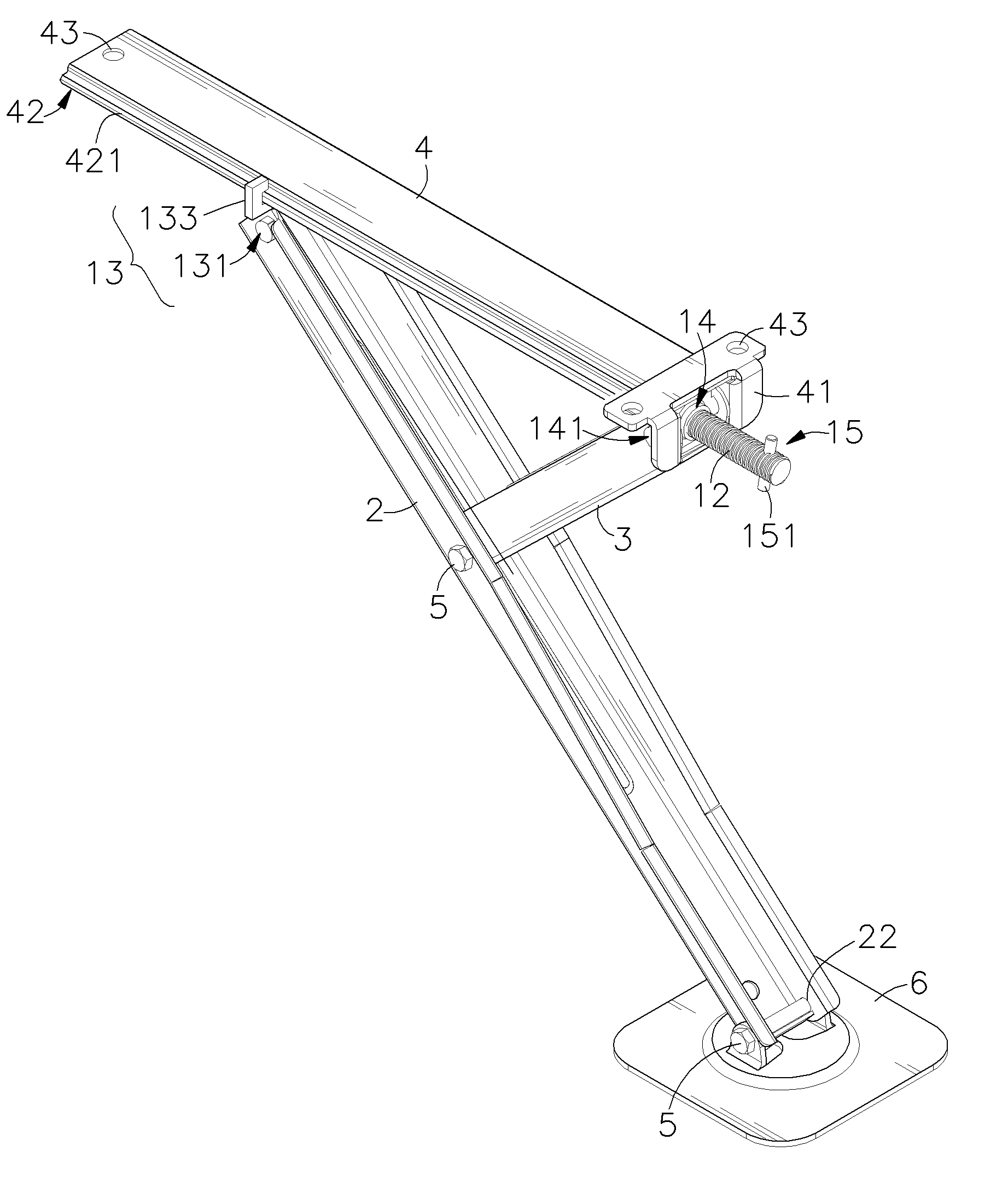
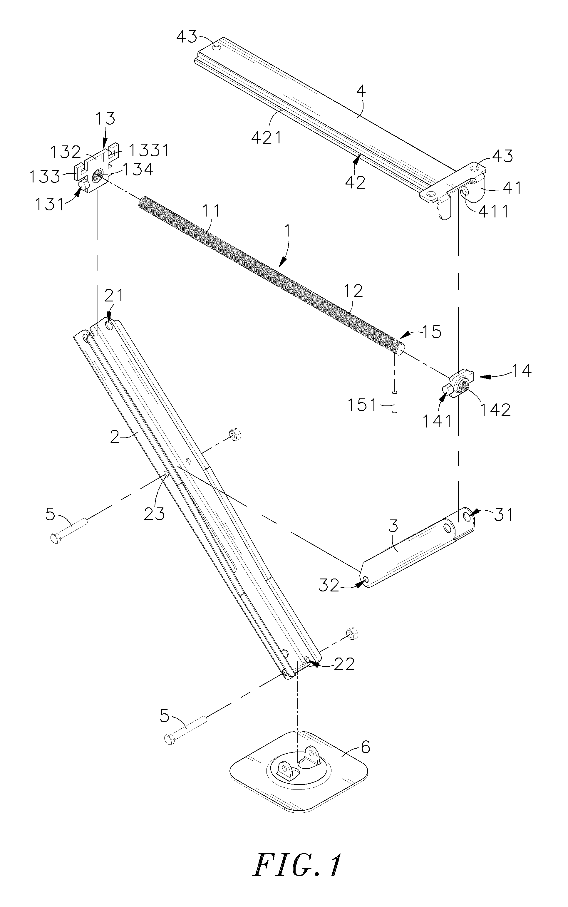
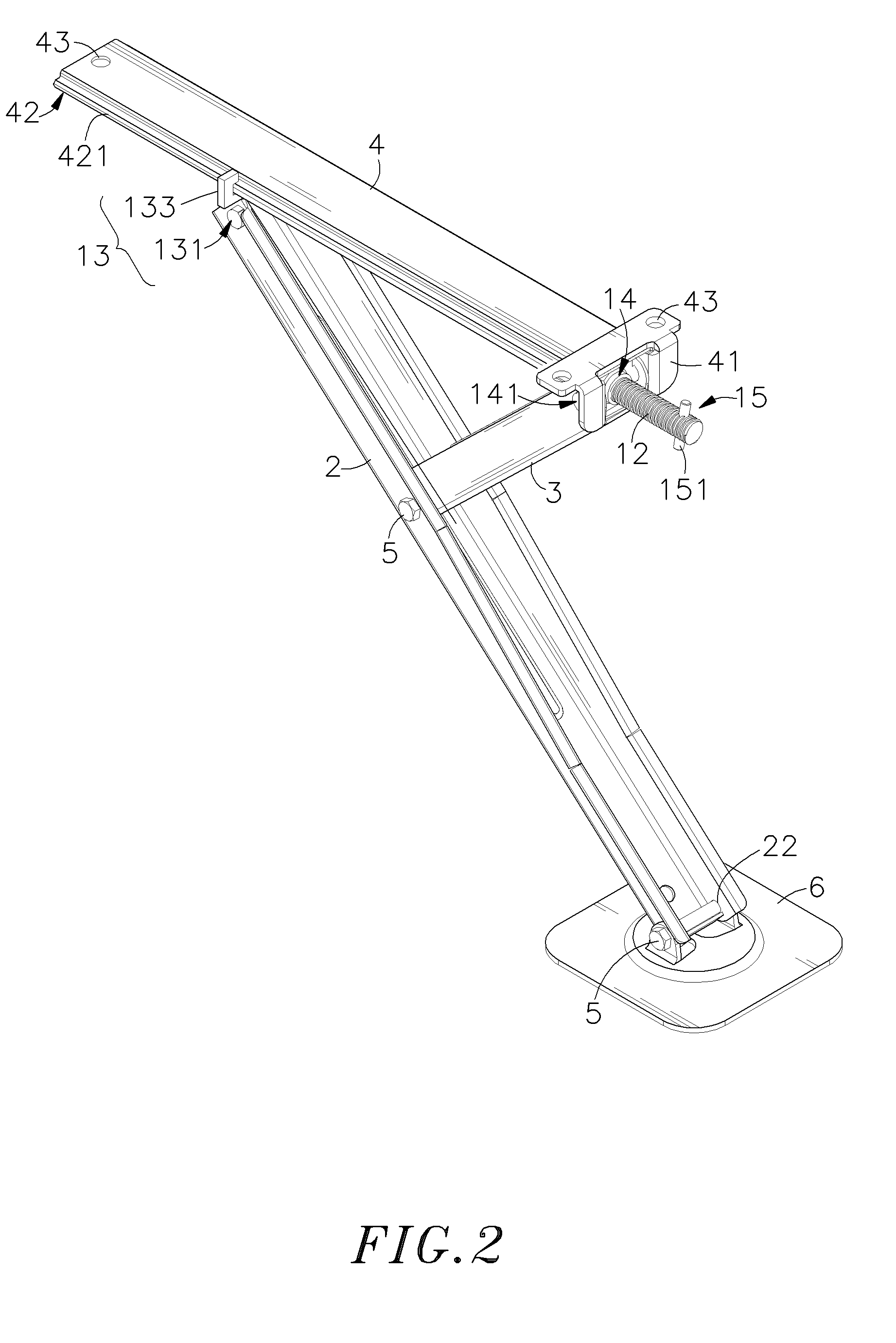
[0021]Referring to FIGS. 1 and 2, an exploded view and an elevational view of an assembly of a supporting device according to an embodiment of the present invention, the quick rising supporting device comprises a bar 1, a supporting arm 2, a swing arm 3 and a top plate 4.

[0022]A first threaded portion 11 and a second threaded portion 12 are respectively formed on two sides of the bar 1. A threading direction of the first threaded portion 11 is different from that of the second threaded portion 12. The first and second threaded portions 11 and 12 are thread connected to a first connecting block 13 and a second connecting block 14 respectively having threaded holes 134 and 142. The first and second connecting blocks 13 and 14 have connection portions 131 and 141 on the two sides thereof and threaded to the distal ends of the supporting arm 2 and the swing arm 3. The first connecting block 13 comprises a supporting block 132 protruding at a top portion thereof, and a sliding block 133 ...


PUM


Abstract

A quick rising supporting device includes a bar having a first threaded portion and a second threaded portion on the two sides respectively with a first connecting block and a second connecting block, and an axial portion on top of a supporting arm and a swing arm forming a Y shape bar are respectively axially connected to the first and second connecting blocks. A sliding block is formed on a side of the first connection block. The translatory shift of the bar on the second connecting block motivates the first connecting block to move in same direction when the bar rotates, the first connecting block is led by the first threaded portion to rotate and move forward to achieve the dual displacement speed of the supporting device. When the closed supporting arm and the swing arm bias and swing to open, only biasing and swinging of the supporting arm and the swing arm is required to open the supporting arm and the swing arm by using a low rotate dynamic strength to rotate the bar, thus the elevation angle between the supporting arm and the swing arm can be quickly opened or closed, and the rising operation can be faster and smoother with less time.

Description

BACKGROUND OF THE INVENTION[0001]1. Field of the Invention[0002]The present invention relates to a quick rising supporting device; and more particularly to a supporting device comprising a bar with two anti directional threaded portions, namely a first threaded portion and a second threaded portion, respectively on two sides of the bar. The first threaded portion comprises a first connecting block thereon for translatory shifting along with the bar, and the second threaded portion comprises a second connecting block thereon for translatory shifting along the bar. The translatory shift of the bar achieves a dual displacement speed with the first and second connecting block to synchronously motivate a supporting rack and a swing arm to move at an elevational angle. Thus, the supporting device can be operated faster along a shortened translatory path with less time and thereby substantially reduce the number of rotations of the bar for the swinging and biasing effect while working with...

Claims


Application Information

Patent Timeline
Patent Type & Authority Applications(United States)
IPC IPC(8): B66F3/36
CPCB66F3/08
Inventor LIU, CHUN-CHIH
Owner MOTECK ELECTRIC CORP
Learn More