Control system for different colors of light emitting diodes

Inactive Publication Date: 2010-06-24
NATIONAL CHI NAN UNIVERSITY
View PDF10 Cites 19 Cited by
  • Summary
  • Abstract
  • Description
  • Claims
  • Application Information

AI Technical Summary

Benefits of technology

[0006]Therefore, an object of the present invention is to provide a control system for different colors of light emitting diodes that can achieve a uni

Problems solved by technology

However, since the conventional control system controls the light emitting diodes to simultaneously emit light during each period, poor light-mixing is pre

Method used


Image

  • Control system for different colors of light emitting diodes
  • Control system for different colors of light emitting diodes
  • Control system for different colors of light emitting diodes

Examples


Embodiment Construction

[0016]Before the present invention is described in greater detail, it should be noted that like elements are denoted by the same reference numerals throughout the disclosure.

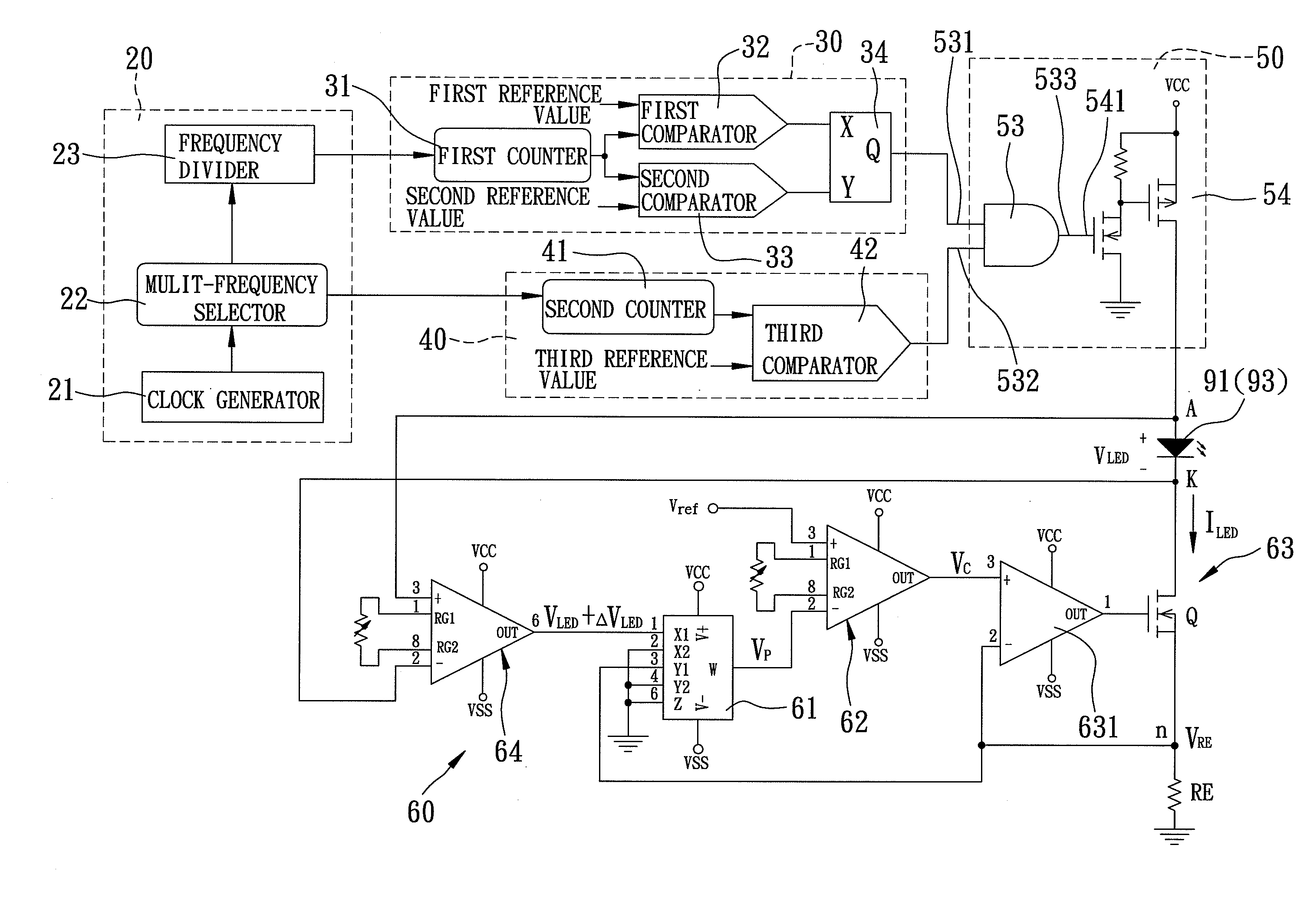
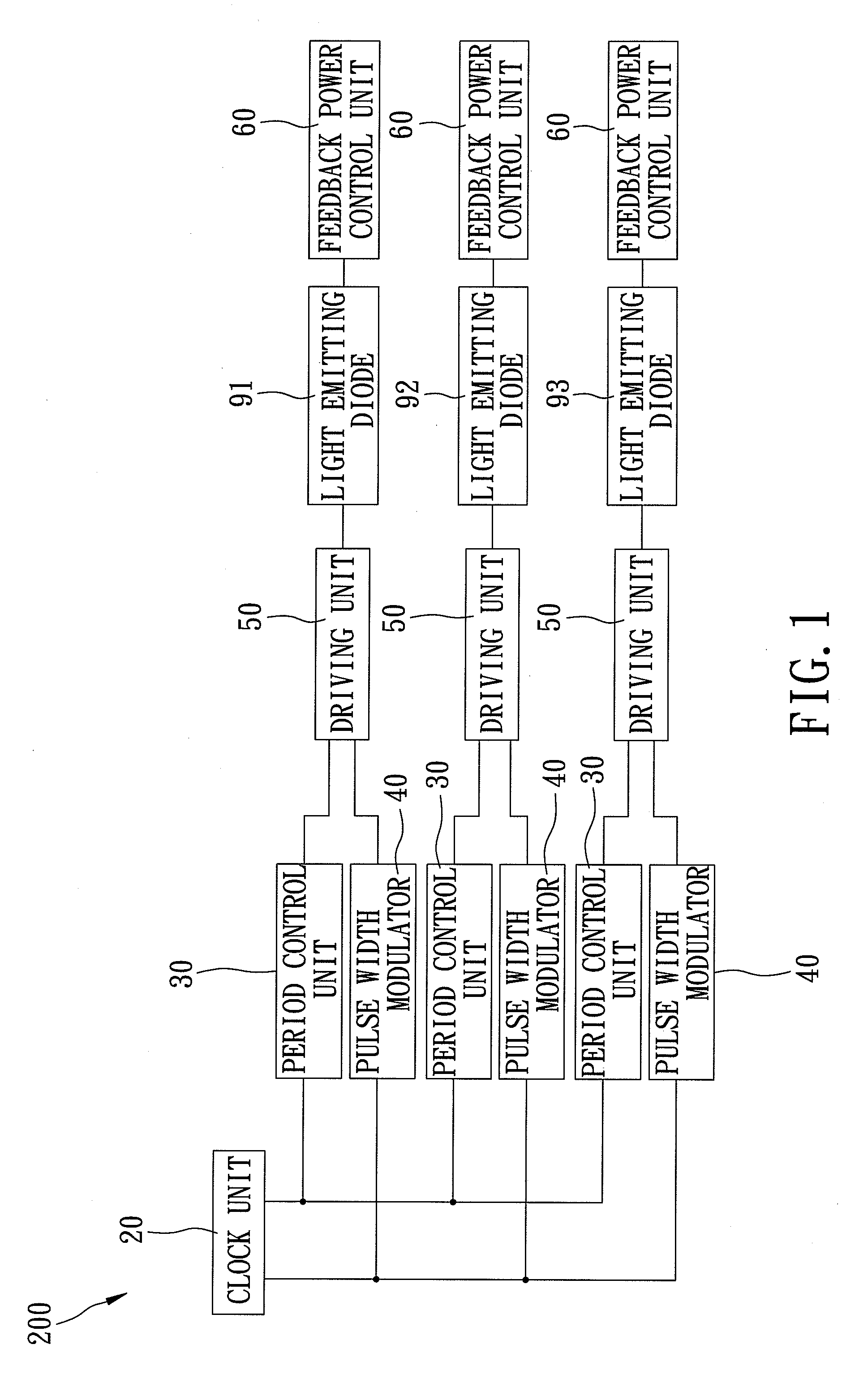
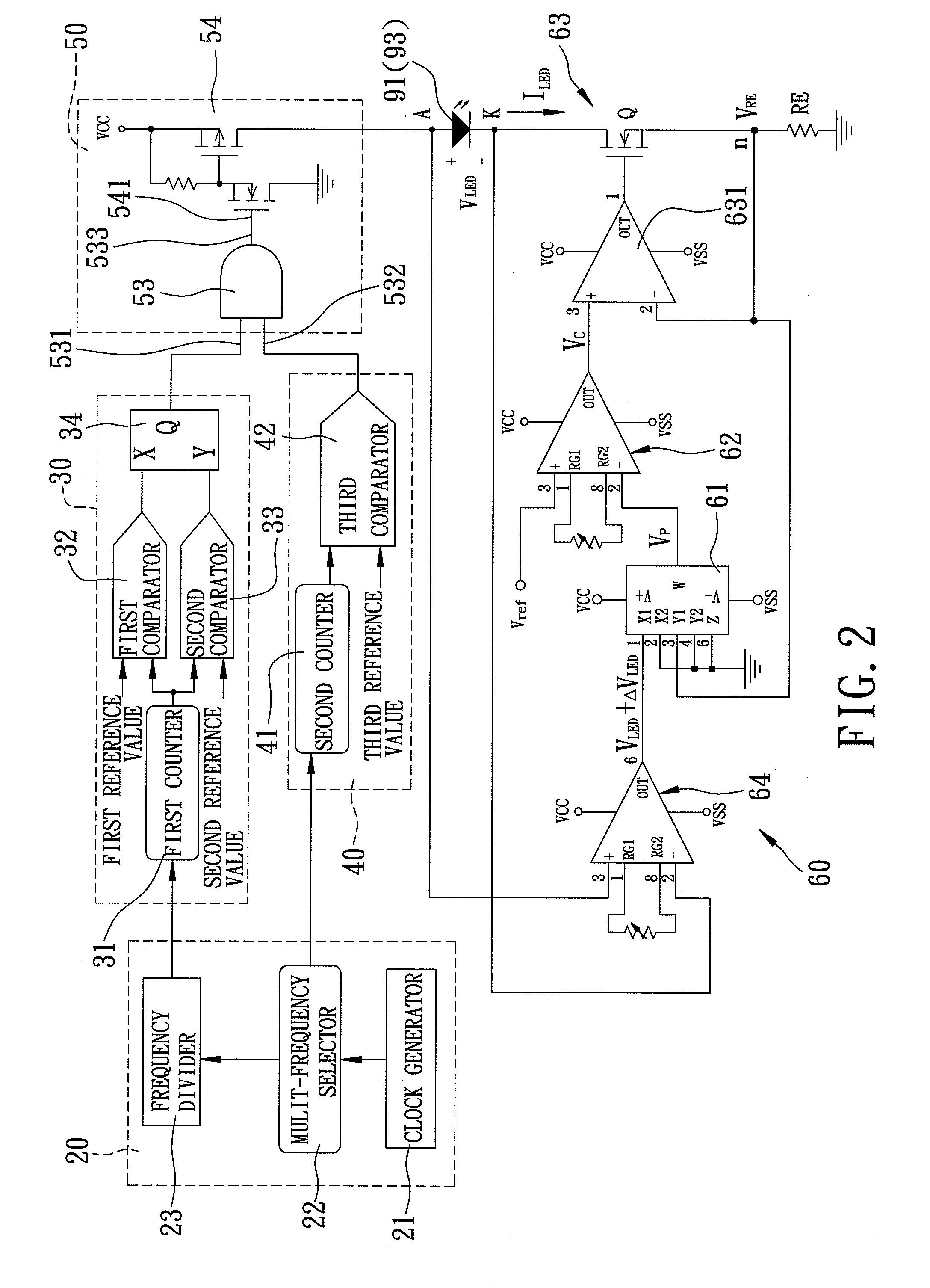
[0017]Referring to FIGS. 1, 2 and 2a, the preferred embodiment of a control system 200 for three light emitting diodes 91, 92, 93 emitting respectively red, green and blue light according to the present invention is shown to include a clock unit 20, and first, second and third control units.

[0018]The clock unit 20 provides a first clock signal, and a second clock signal having a frequency lower than that of the first clock signal. In this embodiment, as shown in FIG. 2, the clock unit 20 includes a clock generator 21, a multi-frequency selector 22 and a frequency divider 23. The clock generator 21 generates a clock signal. The multi-frequency selector 22 is coupled to the clock generator 21, receives the clock signal from the clock generator 21, and outputs the first clock signal to each of the first, second and...


PUM


Abstract

A control system includes a clock unit for providing a first clock signal, and a second clock signal having a frequency lower than that of the first clock signal. Three control units are coupled respectively to three light emitting diodes (LED) emitting respectively three different colors. Each control unit is operable based on the clock signals and a corresponding set of first and second reference values to output a driving pulse signal to a corresponding LED such that the corresponding LED is driven by the driving pulse signal to emit light during a corresponding one of first, second and third time periods of a control cycle of the control system.

Description

BACKGROUND OF THE INVENTION[0001]1. Field of the Invention[0002]The invention relates to a control system, more particularly to a control system for different colors of light emitting diodes.[0003]2. Description of the Related Art[0004]A conventional control system for three different colors of light emitting diodes disclosed in FIG. 9 of U.S. Pat. No. 6,016,038 achieves mixing of light emitted by the light emitting diodes by controlling duty cycles of the light emitting diodes during an exemplary period.[0005]However, since the conventional control system controls the light emitting diodes to simultaneously emit light during each period, poor light-mixing is presented at a periphery of a combination of the light emitting diodes. Therefore, the conventional control system cannot ensure a uniform light-mixing effect.SUMMARY OF THE INVENTION[0006]Therefore, an object of the present invention is to provide a control system for different colors of light emitting diodes that can achieve ...

Claims


Application Information

Patent Timeline
IPC IPC(8): H03K19/096
CPCH03K7/08
Inventor SUN, TAI-PINGWANG, CHIA-HUNGHUNG, TZU-LUNYAN, HENG-YU
Owner NATIONAL CHI NAN UNIVERSITY
Why Eureka
Try Eureka