Swivel Golf Tee

Inactive Publication Date: 2010-06-24
TAN FU HSING
View PDF13 Cites 6 Cited by
  • Summary
  • Abstract
  • Description
  • Claims
  • Application Information

AI Technical Summary

Benefits of technology

[0006]The present invention has been accomplished under the circumstances in view. It is one object of the present invention to provide a swivel golf tee, which avoids production of reaction force against the golf club when the user drives the golf ball.

Problems solved by technology

To lower this reaction force, wooden materails having a relatively lower density may be used for making tee A. However, this method cannot completely eliminate the production of a reaction force when a user drives a golf ball away from a tee.

Method used


Image

  • Swivel Golf Tee
  • Swivel Golf Tee
  • Swivel Golf Tee

Examples


Embodiment Construction

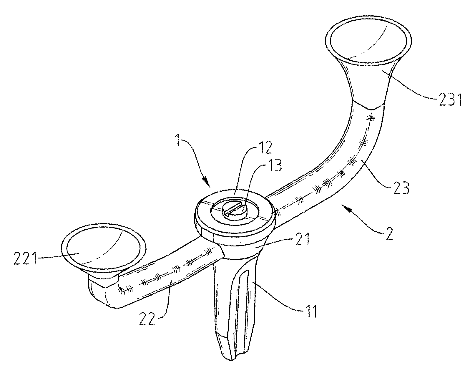
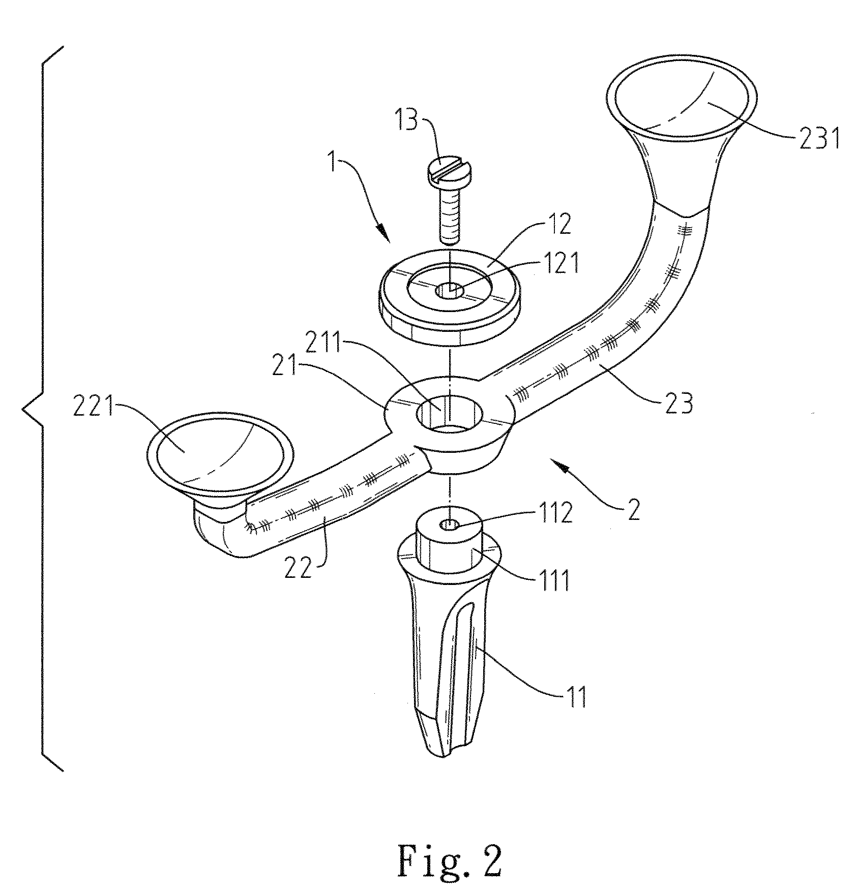
[0013]Referring to FIGS. 1 and 2, a swivel golf tee comprises an anchoring device 1 and a bracket 2.

[0014]The anchoring device 1 comprises a stem 11, which has a top pivot 111 vertically upwardly extended from its top side and a locating hole 112 on the center of the top side of the top pivot 111, a locating member 12, which has a center through hole 121, and a fastening member 13, which is inserted through the center through hole 121 and fastened to the locating hole 112 to affix the locating member 12 to the top side of the top pivot 111.

[0015]The bracket 2 comprises a base 21, a coupling hole 211 cut through the top and bottom sides of the base 21, a first arm 22 and a second arm 23 respectively transversely extended from two opposite lateral sides of the base 21 and respectively smoothly covered upwards and terminating in a respective ball cup 221 or 231.

[0016]During installation of the swivel golf tee, couple the coupling hole 211 of the base 21 of the bracket 2 to the top pivo...


PUM


Abstract

A swivel golf tee includes an anchoring device for fastening to the ground, and a bracket pivoted to the anchoring device and having two arms disposed at two opposite lateral sides and terminating in a respective ball cup for holding a golf ball. The bracket is turned about the anchoring device when the user drives the golf ball away from one ball cup, avoiding reaction force production against the golf club.

Description

BACKGROUND OF THE INVENTION[0001]1. Field of the Invention[0002]The present invention relates to golf tees and more particularly, to a swivel golf tee that avoids production of reaction force against the golf club when the user drives the golf ball.[0003]2. Description of the Related Art[0004]When playing golf, as shown in FIG. 5, a tee A is normally used and fastened to the ground to support a golf ball B for the first stroke of each hole. When driving the golf ball B with a golf club, the golf club will hit the golf ball B at first and then the upper part of the tee A without interruption. When the golf club hits the tee A, a reaction force is produced against the golf club, causing the golf club to bais. At this time, the gall ball B may be not driven toward the expected direction. To lower this reaction force, wooden materails having a relatively lower density may be used for making tee A. However, this method cannot completely eliminate the production of a reaction force when a...

Claims


Application Information

Patent Timeline
IPC IPC(8): A63B57/00
CPCA63B57/0018A63B57/10
Inventor TAN, FU-HSING
Owner TAN FU HSING
Why Eureka
Try Eureka