
Pressurized carbon dioxide bathing apparatus

a technology of carbon dioxide bathing and pressurized carbon dioxide, which is applied in the field of pressurized carbon dioxide bathing apparatus, can solve the problems of low absorption and limited use and achieve the effect of enhancing the permeability of carbon dioxide from the skin and efficiently absorbing from the skin

Inactive Publication Date: 2010-07-01
ACP JAPAN +1
View PDF5 Cites 10 Cited by
  • Summary
  • Abstract
  • Description
  • Claims
  • Application Information

AI Technical Summary

Benefits of technology

[0027]The pressurized carbon dioxide bathing apparatus according to the invention has a cover suit of a two-layer structure which has an enclosed layer for confining a mixed gas of carbon dioxide and water vapor supplied from the carbon dioxide supply means to bring the mixed gas of carbon dioxide and water vapor into direct contact with skin of a living body, while having an enclosed layer for confining compressed air supplied from the compressed air supply means, thereby brings carbon dioxide into contact with skin of the living body by a predetermined pressure value or more using the compressed air, and thus remarkably enhances permeability of carbon dioxide from the skin. Further, since it is not necessary to increase the pressure of the mixed gas of carbon dioxide and water vapor itself, a large amount of carbon dioxide is not required, and it is possible to cause carbon dioxide to be efficiently absorbed from the skin. Furthermore, since carbon dioxide is supplied while being contained in water vapor containing one or a plurality of chemical agents, it is possible to further add effects such as blood circulation promotion, sterilization and the like specific to each chemical agent.

Problems solved by technology

However, the conventional techniques of above-mentioned Patent Documents 1 to 3 are to dissolve carbon dioxide in water in a bath in bathing to be absorbed from skin of the human body, and have problems that the absorptance of carbon dioxide from skin is not high although a large amount of carbon dioxide is consumed.
Further, the use is limited to the time of bathing.

Method used


Image

  • Pressurized carbon dioxide bathing apparatus
  • Pressurized carbon dioxide bathing apparatus
  • Pressurized carbon dioxide bathing apparatus

Examples


embodiment 1

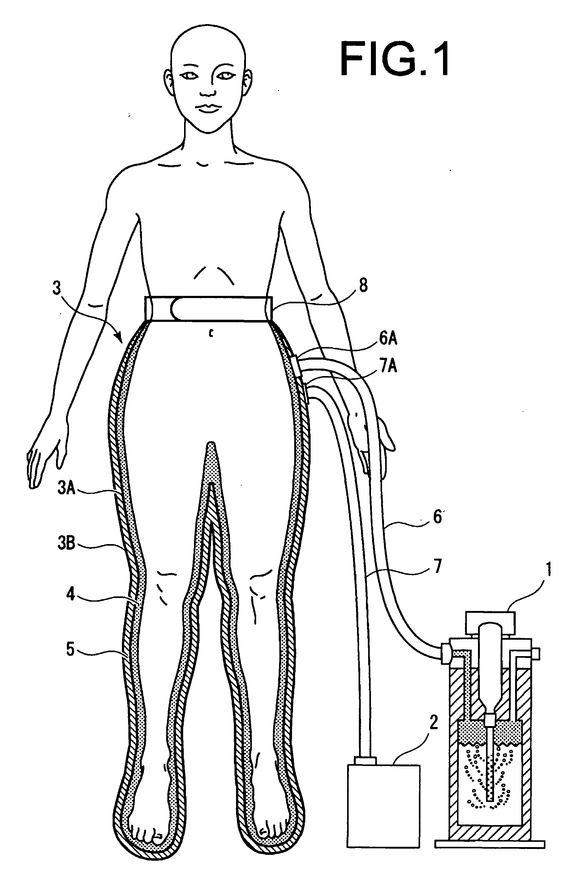
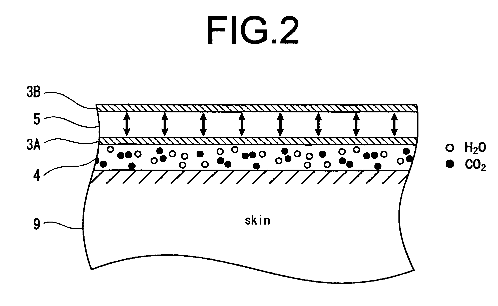
[0059]FIG. 1 is an entire schematic view of a pressurized carbon dioxide bathing apparatus (for the lower body) according to Embodiment 1 of the invention. Further, FIG. 2 is a principal-part enlarged view showing the contact relationship between the cross section of the cover suit and skin, and FIG. 3 is a schematic view of a carbon dioxide supply apparatus.

[0060]As shown in FIG. 1, the pressurized carbon dioxide bathing apparatus according to this Embodiment is comprised of a carbon dioxide supply apparatus 1 for supplying carbon dioxide being contained in water vapor, a compressor 2 for supplying compressed air, a cover suit 3 with integrally formed inner cover suit 3A that covers the human body (herein, the lower body as an example) and that is filled with the mixed gas of carbon dioxide and water vapor to cause the mixed gas to contact skin of this area to be absorbed, and outer cover suit 3B that is filled with compressed air to pressurize the mixed gas inside the inner cover ...

embodiment 2

[0072]FIG. 4 is a schematic view of a pressurized carbon dioxide bathing apparatus (for the upper body) according to Embodiment 2 of the invention.

[0073]Described herein is a pressurized carbon dioxide bathing apparatus for the purpose of performing pressurized carbon dioxide bathing on the upper body. In addition, in FIG. 4, parts with the same configurations as in FIG. 1 are assigned the same reference numerals to omit descriptions thereof.

[0074]In FIG. 4, a cover suit 30 is formed from an inner cover suit 30A and outer cover suit 30B. The inner cover suit 30A and outer cover suit 30B are formed integrally, to the inside of the inner cover suit 30A is supplied the mixed gas of carbon dioxide and water vapor from the carbon dioxide supply apparatus 1, and to the inside of the outer cover suit 30B is supplied compressed air from the compressor 2. By this means, a mixed gas layer 31 of carbon dioxide and water vapor is formed between the inner cover suit 30A and skin, and a pressuriz...

embodiment 3

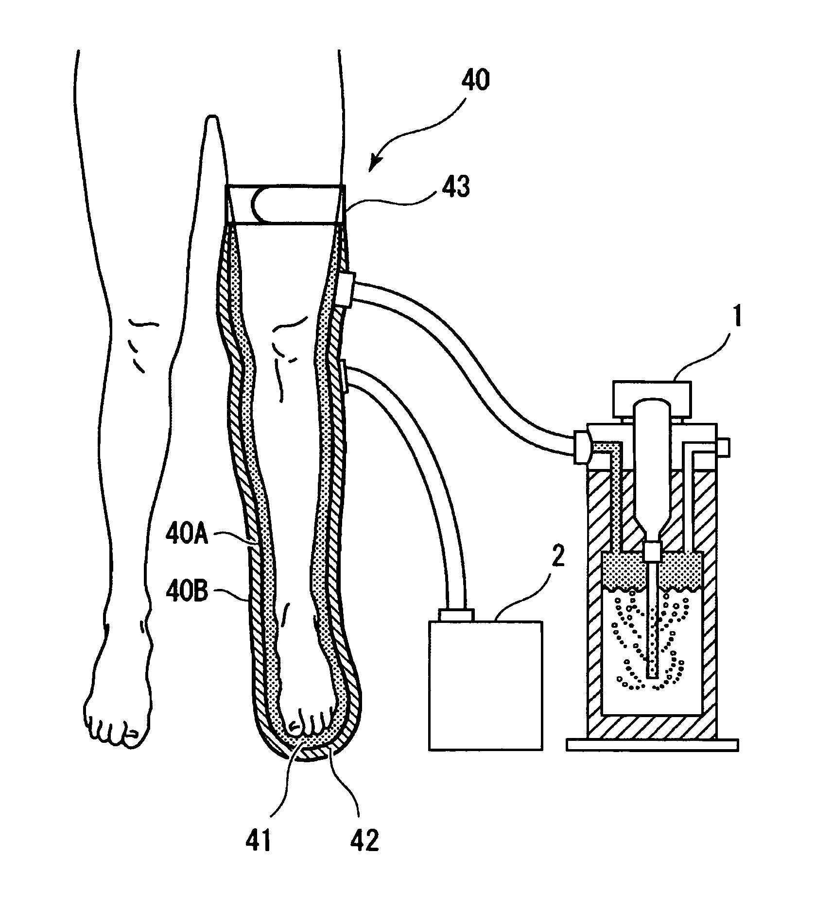
[0076]FIG. 6 is a schematic view of a pressurized carbon dioxide bathing apparatus (for the single lower limb) according to Embodiment 3 of the invention.

[0077]Described herein is a pressurized carbon dioxide bathing apparatus for the purpose of performing pressurized carbon dioxide bathing on the single lower limb. In addition, in FIG. 5, parts with the same configurations as in FIG. 1 are assigned the same reference numerals to omit descriptions thereof.

[0078]In FIG. 5, a cover suit 40 is formed from an inner cover suit 40A and outer cover suit 40B. The inner cover suit 40A and outer cover suit 40B are formed integrally, to the inside of the inner cover suit 40A is supplied the mixed gas of carbon dioxide and water vapor from the carbon dioxide supply apparatus 1, and next, to the inside of the outer cover suit 40B is supplied compressed air from the compressor 2. By this means, a mixed gas layer 41 of carbon dioxide and water vapor is formed between the inner cover suit 40A and s...


PUM


Abstract

Provided is a pressurized carbon dioxide bathing apparatus for bringing carbon dioxide into contact with skin of a living body by a predetermined pressure value or more using compressed air, and thereby enabling carbon dioxide to be absorbed efficiently from the skin, and the pressurized carbon dioxide bathing apparatus is comprised of a carbon dioxide supply means 1 for supplying a mixed gas of carbon dioxide and water vapor containing one or a plurality of chemical agents, a compressed air supply means 2, and a cover suit 3 of a two-layer structure having an enclosed layer 4 that is connected to the carbon dioxide supply means 1 via a connector 6 to confine the mixed gas supplied from the carbon dioxide supply means 1 so as to bring the mixed gas into direct contact with skin of the human body and an enclosed layer 5 that is connected to the compressed air supply means 2 via a connector 7 to confine compressed air supplied from the compressed air supply means 2, where the carbon dioxide is brought into contact with skin of the human body with a predetermined pressure value or more by the compressed air.

Description

TECHNICAL FIELD [0001]The present invention relates to a pressurized carbon dioxide bathing apparatus for bringing carbon dioxide into direct contact with skin of a living body, thereby enlarging the blood vessel and improving the blood circulation, and more particularly, to a pressurized carbon dioxide bathing apparatus for bringing carbon dioxide into contact with skin of a living body by a predetermined pressure value or more using compressed air, and thereby enhancing absorption efficiency of carbon dioxide from the skin.BACKGROUND ART [0002]Conventionally, it has been known that the blood vessel is enlarged when carbon dioxide (CO2) is absorbed from skin of a living body. Carbon dioxide penetrates skin by simply contacting the skin, enlarges the blood vessel of the penetration site, improves the blood circulation, and therefore, exerts various physiological effects of reducing the blood pressure, easing loads on the heart, improving metabolism, promoting the elimination of pain...

Claims


Application Information

Patent Timeline
Patent Type & Authority Applications(United States)
IPC IPC(8): A61M37/00
CPCA61H33/14A61H2033/145A61H2205/08A61H2205/10A61H9/0078A61M35/00A61M35/30
Inventor NAKAMURA, SHOICHI
Owner ACP JAPAN
Learn More