Ulnar osteotomy plate including increased compression

a technology of osteotomy plate and ulnar bone, which is applied in the field of medical implants, can solve the problems of reducing the effect of osteotomy and reducing the difficulty of surgery, and achieves the effect of shortening the procedure and shortening the procedur

Inactive Publication Date: 2010-07-01
SCHUMER EVAN D
View PDF102 Cites 66 Cited by
  • Summary
  • Abstract
  • Description
  • Claims
  • Application Information

AI Technical Summary

Benefits of technology

[0013]Briefly, according to an embodiment of the present invention, an ulnar osteotomy plate for use in an ulnar shortening osteotomy is disclosed. The ulnar osteotomy plate includes an elongated metallic plate having tapered ends, wherein the plate is concave in a direction perpendicular to a main axis of the plate. The ulnar osteotomy plate further includes a plurality of holes along the main axis of the plate, wherein the plurality of holes includes a substantially elliptical hole with a beveled interior edge located on a first side of the plate and a threaded hole located on a second side of the plate.
[0014]In another embodiment of the present invention, a system for performing an ulnar shortening osteotomy is disclosed. The system includes an elongated metallic plate having tapered ends, wherein the plate is concave in a direction perpendicular to a main axis of the plate. The ulnar osteotomy plate includes a plurality of holes along the main axis of the plate, wherein the plurality of

Problems solved by technology

Secondly, the two newly cut ends of the bone must be rigidly affixed to allow a solid bone mass to form between them during the healing process.
Various problems, however, can arise during an ulnar shortening osteotomy.
One problem associated with performing an ulnar shortening osteotomy freehand (without the use of a cutting guide) involves maintaining the bone in a fixed position during cutting such that the two remaining surfaces of the cut bone are uniform and planar.
When no cutting guide is used, it can be difficult to hold the cutting tool and the bone in place using just the surgeon's hands.
Again, this can be challenging using only a surgeon's hands.
Keeping the cutting tool and bone stationary, as well as alignment of the ends of cut bone, can also be a problem when a cutting guide is used.
Another problem associated with using a cutting tool is the increased number of devices or parts necessary to perform the ulnar shortening osteotomy.
The increased number of parts used in this process can be complicated for the surgeon and increases the risk of misuse and/or user error.
Although this approach provides a level of attachment, the cutting guide may still fall out when vibrations are experienced.
When reattaching the two cut bone ends using a plate, compression of the two ends of bone can be a problem.
This arrangement may provide compression between the plate an

Method used


Image

  • Ulnar osteotomy plate including increased compression
  • Ulnar osteotomy plate including increased compression
  • Ulnar osteotomy plate including increased compression

Examples


Embodiment Construction

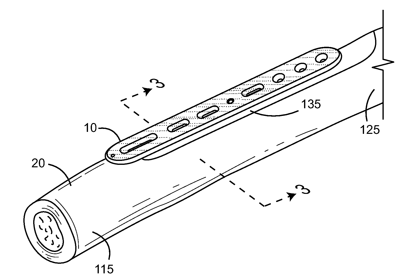
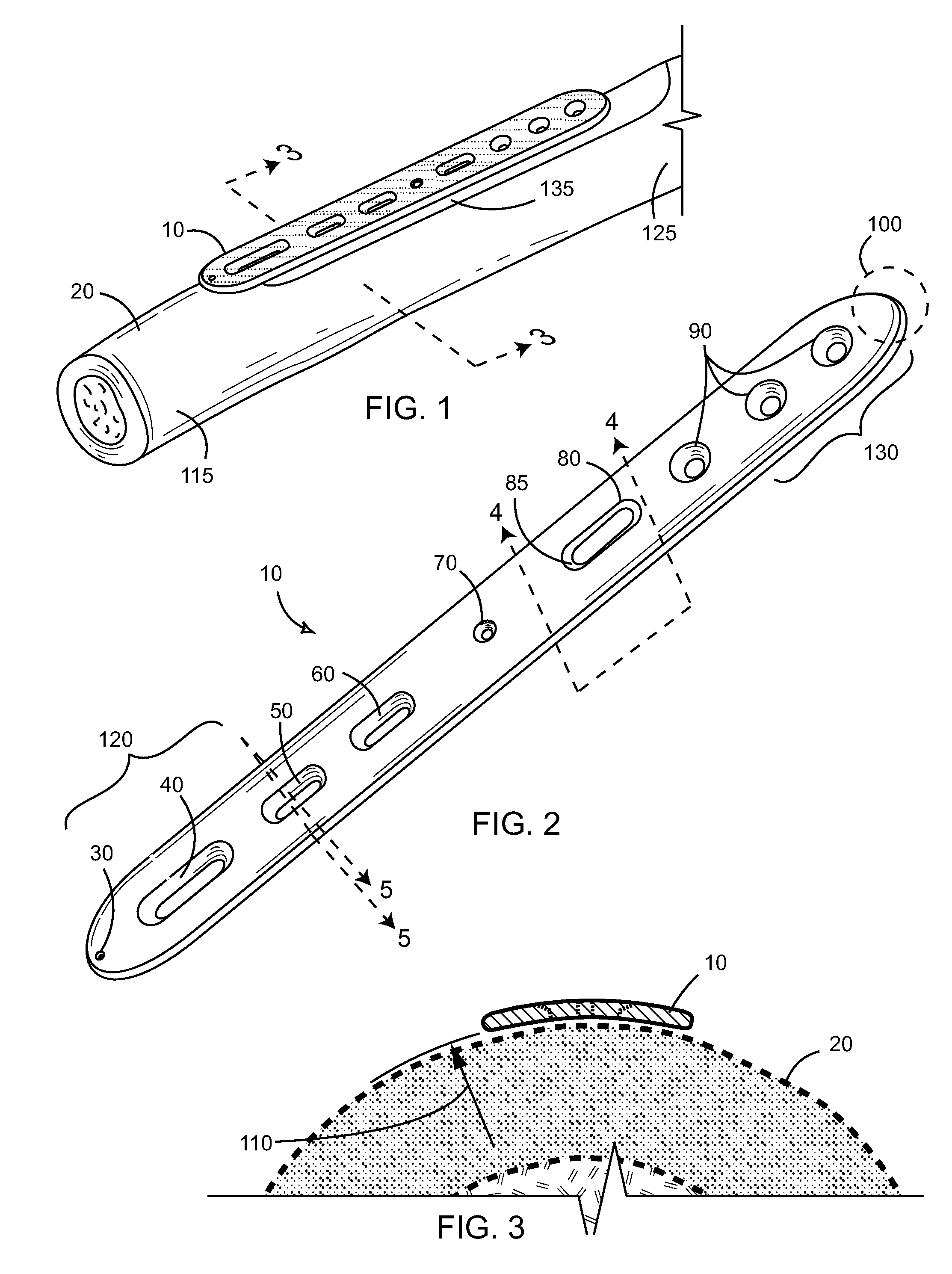
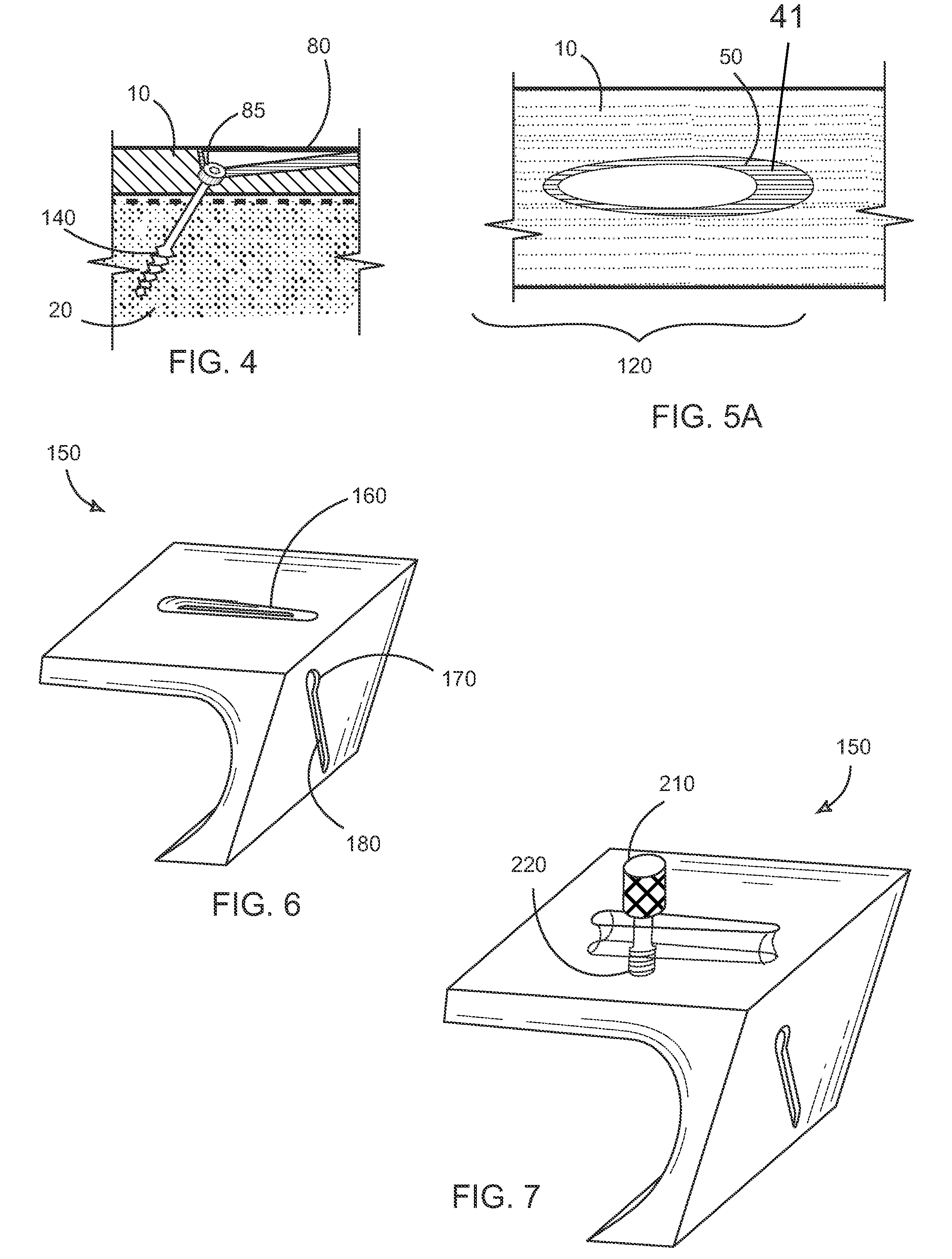
[0044]In one embodiment of the present invention, a system for performing an ulnar shortening osteotomy is disclosed. The system includes an elongated metallic plate having tapered ends, wherein the plate is concave in a direction perpendicular to a main axis of the plate. The ulnar osteotomy plate includes a plurality of holes along the main axis of the plate, wherein the plurality of holes includes a substantially elliptical hole with a beveled interior edge located on a first side of the plate and a threaded hole located on a second side of the plate. The system also includes a first screw for insertion into one end of the elliptical hole and further into an ulna underneath the plate, wherein the first screw includes a beveled edge underneath a head such that when the beveled edge of the first screw contacts the beveled interior edge of the elliptical hole, there results a force along the main axis towards the first side. The system also includes a second screw for insertion into...


PUM


Abstract

The present invention provides an ulnar osteotomy plate for use in an ulnar shortening osteotomy. The ulnar osteotomy plate includes an elongated metallic plate having tapered ends, wherein the plate is concave in a direction perpendicular to a main axis. The ulnar osteotomy plate further includes a plurality of holes along the main axis, wherein the plurality of holes includes a substantially elliptical hole with a beveled interior edge located on a first side of the plate and a threaded hole located on a second side of the plate. A first screw is inserted into one end of the elliptical hole and further into an ulna underneath the plate, wherein the first screw includes a beveled edge underneath a head. A second screw is inserted into the threaded hole and further into the ulna, wherein the second screw includes a portion of the shaft near a head to be threaded.

Description

FIELD OF THE INVENTION[0001]The invention disclosed broadly relates to the field of medical implants, and more particularly relates to medical implants used for ulnar osteotomies.BACKGROUND OF THE INVENTION[0002]An osteotomy, well known in the orthopaedic arts, is a surgical operation whereby a bone is cut to shorten, lengthen, or change its alignment. An osteotomy consists of the cutting of a portion of bone and the joining of the resulting pair of free ends of bone. First, the bone is cut in a precise way to correct whatever deformity or congenital problem exists. Secondly, the two newly cut ends of the bone must be rigidly affixed to allow a solid bone mass to form between them during the healing process.[0003]Typically, bone cuts in an osteotomy are accomplished either free hand, or with the use of a “jig” or other cutting guide that is applied to the bone and then removed after the cuts have been created. Once this has been accomplished, the cut bone ends are rigidly held toget...

Claims


Application Information

Patent Timeline
IPC IPC(8): A61B17/70A61B17/04
CPCA61B17/151A61B17/1659A61B17/1686A61B17/8014A61B17/8019A61B17/8052A61B17/8057A61B17/1782
Inventor SCHUMER, EVAN D.
Owner SCHUMER EVAN D
Why Eureka
Try Eureka