Deflectable sheath introducer

Active Publication Date: 2010-07-01
BIOSENSE WEBSTER INC
View PDF64 Cites 165 Cited by
  • Summary
  • Abstract
  • Description
  • Claims
  • Application Information

AI Technical Summary

Benefits of technology

[0007]The present invention is directed to a deflectable sheath introducer having a shaft through which a catheter, needle or device can extend, and a control handle incorporating a deflection assembly that an operator can manipulate for deflecting a deflectable region near a distal section of the shaft, wherein the deflection assembly has a deflection member, a rotatable rocker member and at least a pulley that is engaged with a portion of a tensile member. Rotation of the deflection member about an axis generally perpendicular to a longitudinal axis of the control handle draws on the tensile member to deflect the shaft.
[0008]In one embodiment, the introducer has a shaft with a central lumen, a control handle with a deflection assembly, and tensile members each with a distal portion extending along opposing sides of within the shaft and a proximal portion extending within the control handle. The deflection assembly has a deflection arm, and a rocker member rotationally coupled to the deflection arm, wherein the rocker member has at least two pulleys, each engaged with a respective proximal tensile member portion. Rotation of the deflection arm in one direction draws one proximal tensi

Problems solved by technology

Deflectable sheaths are also known, however, the deflection mechanism rotates around the axis of the control handle which facilitates two-handed manipulation but is not ideal for single-handed deflection.
Thus, the operator cannot simultaneously deflect the sheath and the catheter extending through the sheath.
Existing sheaths also use a soft distal ti

Method used


Image

  • Deflectable sheath introducer
  • Deflectable sheath introducer
  • Deflectable sheath introducer

Examples


Embodiment Construction

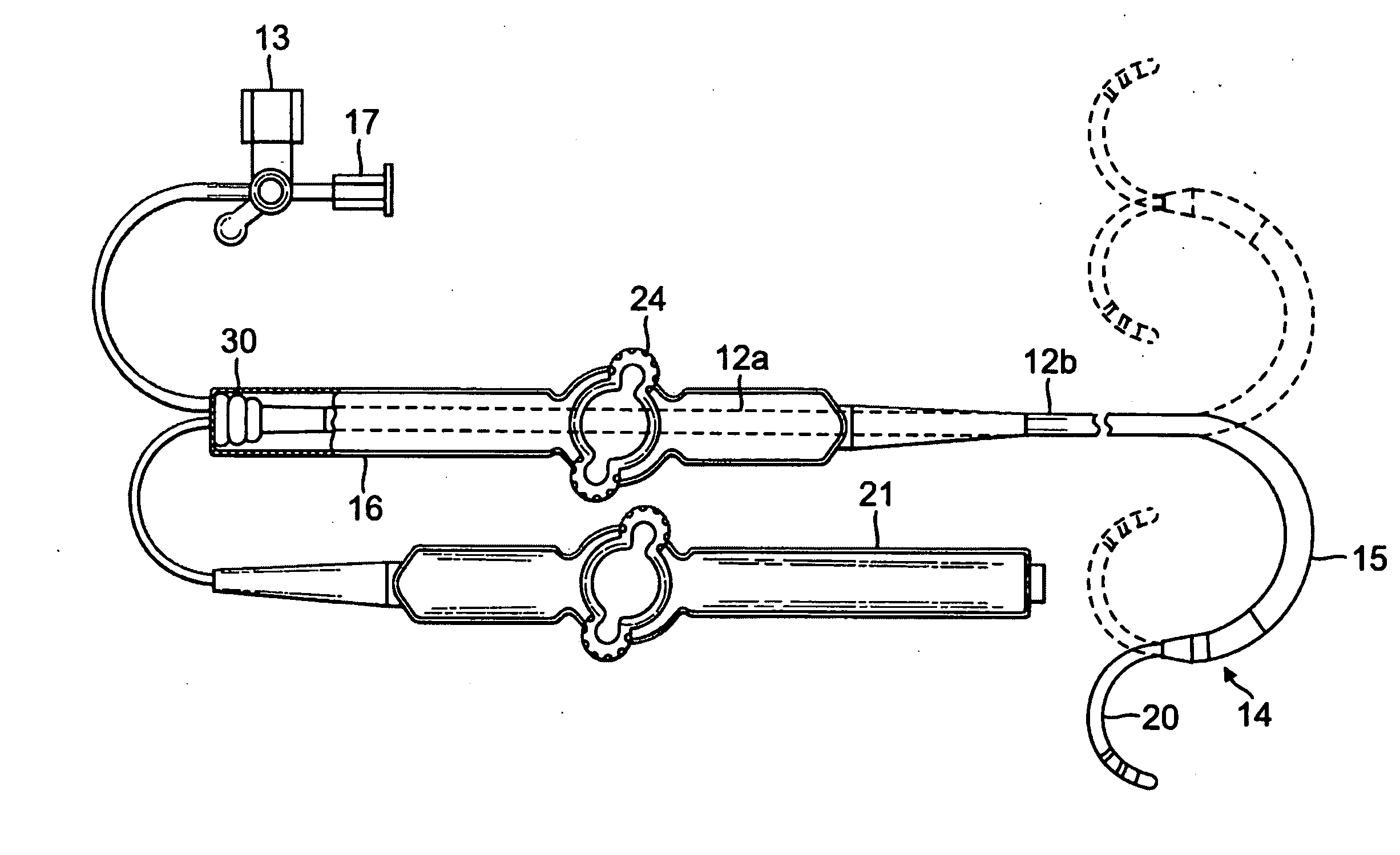
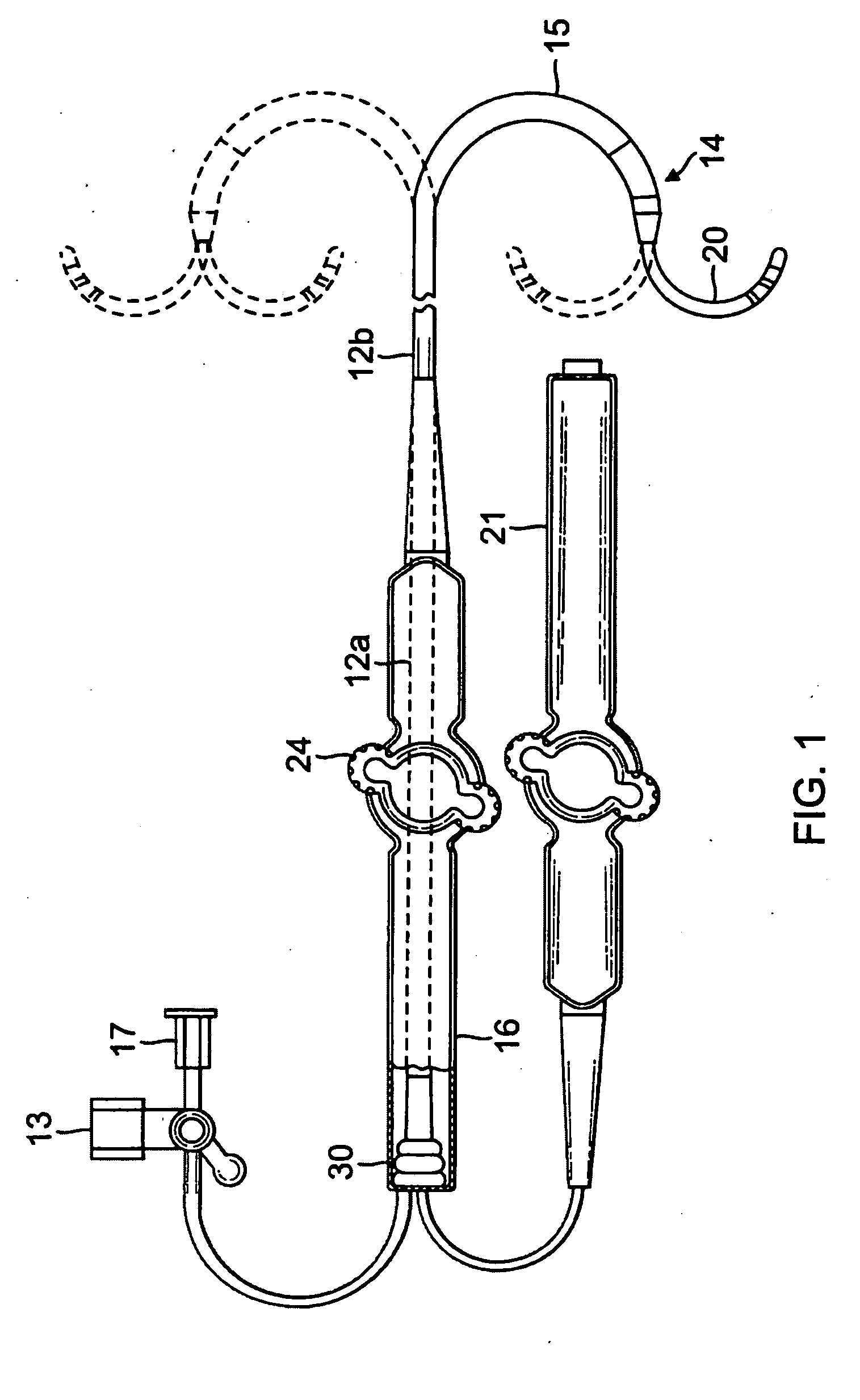
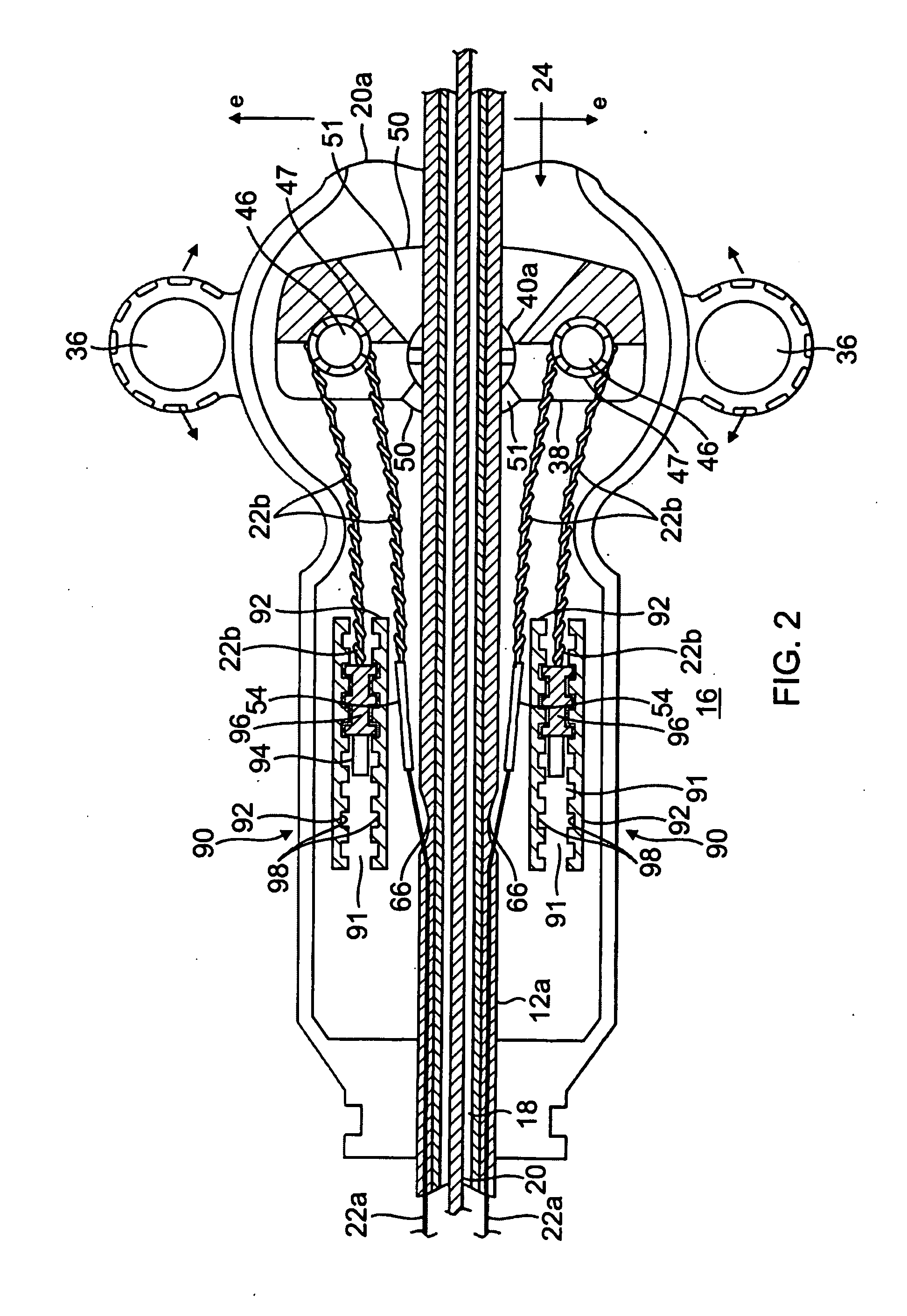
[0036]FIGS. 1 and 2 illustrate an embodiment a steerable bidirectional sheath introducer 10 for use with a catheter, needle or other device 20 (used interchangeably herein) to be extended through the introducer 10 for entry into a patient's body. The introducer 10 comprises an elongated shaft 12, and a control handle 16 at the proximal end of the shaft 12. Distally, the shaft 12 has a deflectable section 15 and a distal tip section 14. The shaft 12 has a central lumen 18 that extends its entire length for passage of the catheter or other device 20. The shaft 12 extends both distally of the control handle 16 and proximally through the control handle.

[0037]For deflecting the deflectable section 15 of the shaft 12, tensile members 22 are provided, with their distal ends anchored at or near the distal tip section 14 and their proximal ends anchored in the control handle 16. Longitudinal movement of the tensile members relative to the shaft 12, which results in deflection of the deflecta...


PUM


Abstract

An introducer has a shaft with a central lumen, a control handle with a deflection assembly, and a tensile member with a distal portion extending along opposing sides of within the shaft and a proximal portion extending within the control handle. The deflection assembly has a deflection arm, and a rotatable member rotationally coupled to the deflection arm, wherein the rocker member has at least one pulley engaged with the proximal tensile member portion. Rotation of the deflection arm in one direction draws the proximal tensile member portion for deflecting the shaft.

Description

FIELD OF INVENTION[0001]The present invention relates to sheath introducers for use with catheters, and in particular, deflectable sheath introducers with control handles.BACKGROUND OF INVENTION[0002]Electrode catheters have been in common use in medical practice for many years. They are used to stimulate and map electrical activity in the heart and to ablate sites of aberrant electrical activity. In use, the electrode catheter is inserted into a major vein or artery, e.g., femoral artery, and then guided into the chamber of the heart which is of concern. Within the heart, the ability to control the exact position and orientation of the catheter tip is critical and largely determines how useful the catheter is.[0003]The Seldinger technique is a medical procedure for insertion of heart catheters including central venous catheters. It is named after Dr. Sven-Ivar Seldinger (1921-1998), a Swedish radiologist. The technique involves puncturing the vein and inserting a guiding sheath, a ...

Claims


Application Information

Patent Timeline
IPC IPC(8): A61N1/00
CPCA61M25/0136A61B2017/00327A61M25/0133A61M2025/015A61M25/0147
Inventor SCHULTZ, JEFFREY W.
Owner BIOSENSE WEBSTER INC
Why Eureka
Try Eureka