System and method for terminating tubing

a technology of terminating system and tubing, which is applied in the direction of drilling pipe, drilling casing, borehole/well accessories, etc., can solve the problems of large and bulky, the method of terminating control line in the wellhead component is problematic, and the damage to the surface components of the well may be destroyed or damaged

Active Publication Date: 2010-07-08
VAULT PRESSURE CONTROL LLC
View PDF1 Cites 13 Cited by
  • Summary
  • Abstract
  • Description
  • Claims
  • Application Information

AI Technical Summary

Problems solved by technology

For example, the surface components of a well may be destroyed or damaged by the wind and waves produced by a hurricane.
However, this method for terminating a control line in a wellhead component is problematic.
Wellhead components may be quite large and bulky, thereby making machining operations on them difficult and time consuming.
Forming a seating surface, s

Method used


Image

  • System and method for terminating tubing
  • System and method for terminating tubing
  • System and method for terminating tubing

Examples


Embodiment Construction

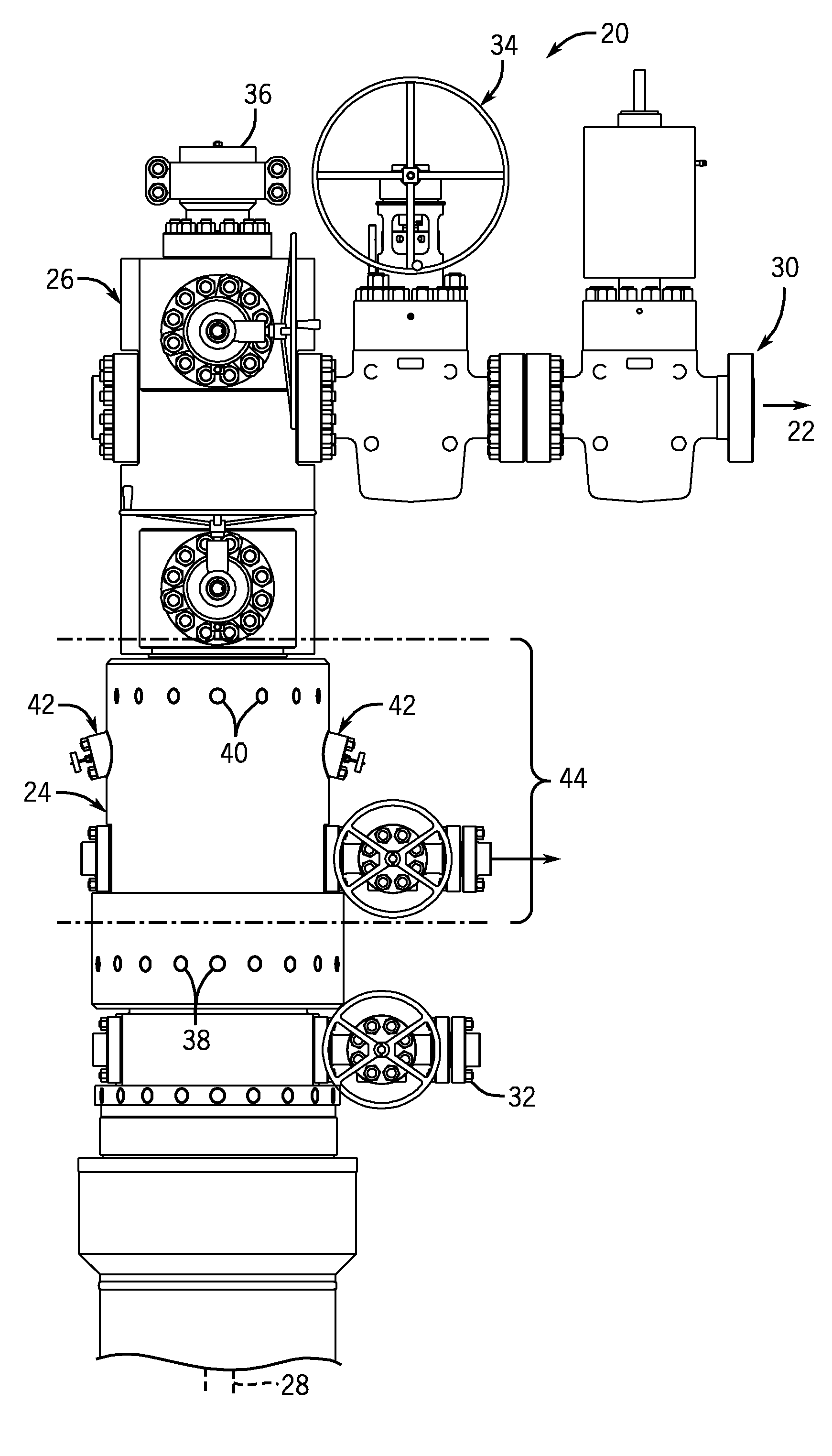
[0016]Referring now to FIG. 1, the present invention will be described as it might be applied in conjunction with an exemplary technique, in this case a well completion assembly for directing oil and / or gas from a well to transmission pipelines or a storage facility, as represented generally by reference numeral 20. In this embodiment, the well completion assembly 20 is a standard tree. However, the technique may be used in trees other than a standard tree or any other type of device where a seal is desired to be formed around tubing extending through an object.

[0017]In the illustrated embodiment, the well completion assembly 20 comprises a tubing head assembly 24 and a block valve 26. The bottom of the tubing head assembly 24 may be connected to a spool (not shown). Wellbore fluid 22 is transported to the tubing head assembly 24 via production tubing 28. The production tubing 28 enters the bottom of the tubing head assembly 24. Wellbore fluid 22 exits the tubing head assembly 24 vi...


PUM


Abstract

A technique is provided for terminating tubing. In the technique, a tubing termination assembly is used to terminate control line tubing from a downhole safety valve at a wellhead component. The tubing termination assembly utilizes a seal ring to form a seal around control line tubing extending from a port through a wellhead component. A seating surface is provided in the seal ring, rather than in the wellhead component, to which a seal member is abutted to form the seal with the control line tubing. The seal ring also comprises a threaded portion to enable a threaded member to urge the seal member against the seating surface.

Description

BACKGROUND[0001]The invention relates generally to a system and method of terminating tubing that extends through a member. In particular, the invention relates to a system and method for terminating tubing that extends through a wellhead component.[0002]A downhole safety valve is a safety feature used in oil and gas wells. As its name implies, a downhole safety valve is located in a well at a point below the surface of the ground. The purpose of a downhole safety valve is to prevent an uncontrollable release of fluids from an underground reservoir in the event of damage to the surface components of a well. For example, the surface components of a well may be destroyed or damaged by the wind and waves produced by a hurricane. In such a scenario, the reservoir fluids could flow to the surface and be released into the environment if a downhole safety valve was not in service. Downhole safety valves commonly are unidirectional valves that are oriented in the well's production tubing su...

Claims


Application Information

Patent Timeline
IPC IPC(8): E21B33/068E21B33/04
CPCE21B33/04E21B33/068
Inventor BORAK, JR., EUGENE A.
Owner VAULT PRESSURE CONTROL LLC
Why Eureka
Try Eureka