Contact lens

a technology of contact lenses and lenses, applied in the field of contact lenses, can solve the problems of less physiological tolerance and create discomfort, and achieve the effect of enhancing physiological tolerance, enhancing comfort, and improving vision quality

Active Publication Date: 2010-07-08
LAB PRECILENS
View PDF4 Cites 60 Cited by
  • Summary
  • Abstract
  • Description
  • Claims
  • Application Information

AI Technical Summary

Benefits of technology

[0013]The disclosure provides for enhancing the com

Problems solved by technology

Because of its relative thickness, the lower edge of the lenses with lower

Method used


Image

  • Contact lens
  • Contact lens
  • Contact lens

Examples


Embodiment Construction

[0040]In all of these figures, identical or similar reference numbers indicate identical or similar members or sets of members.

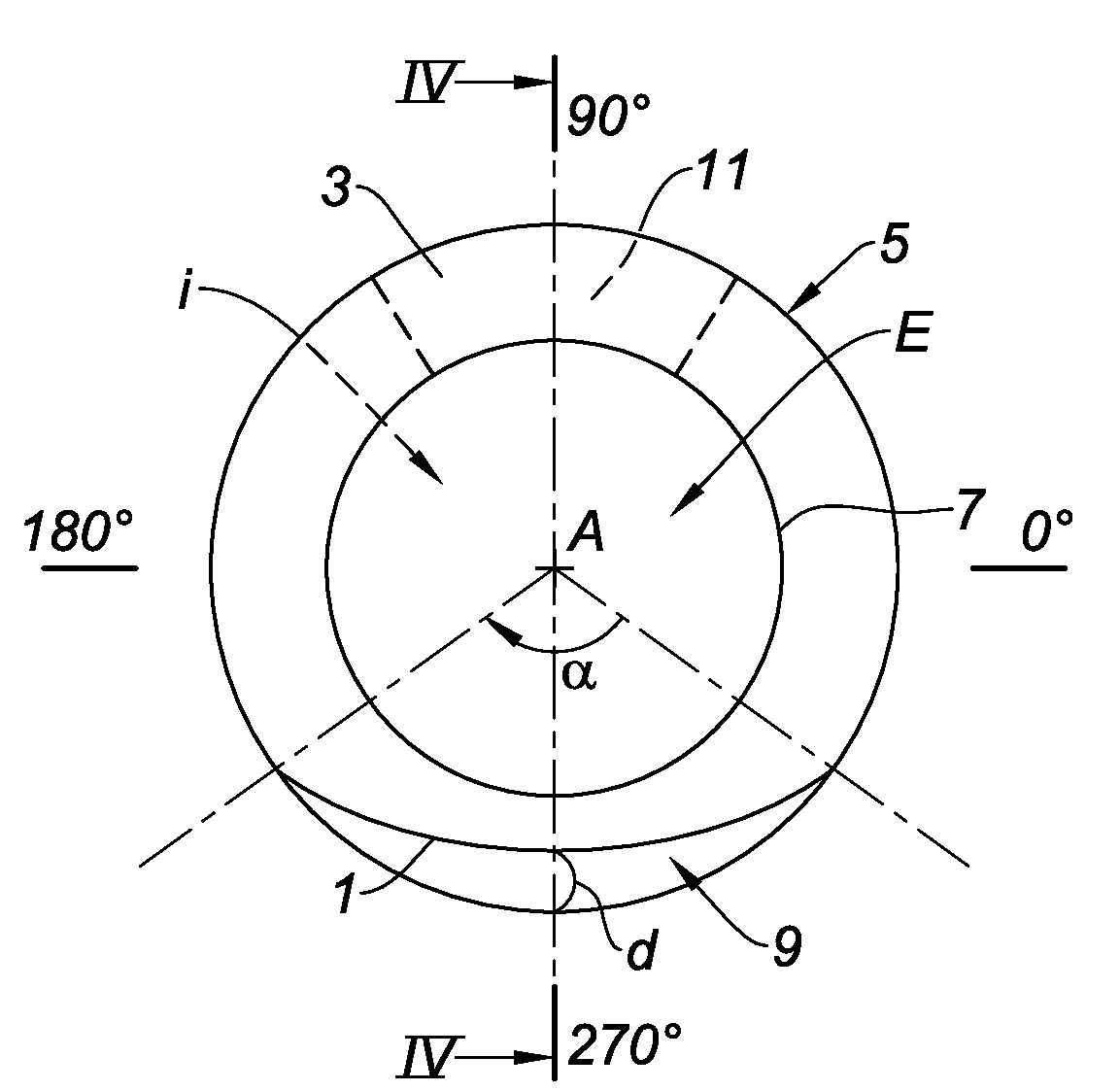
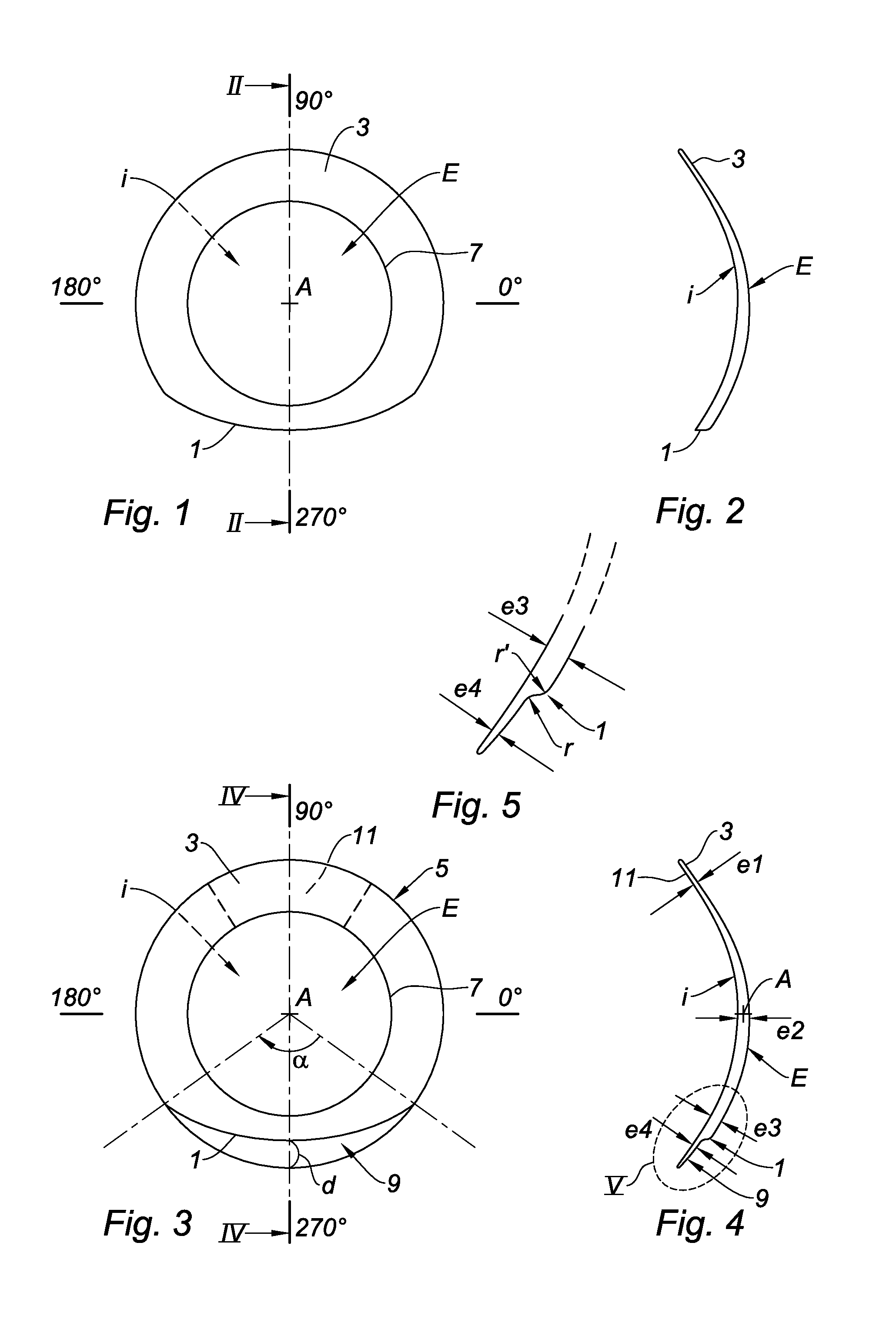
[0041]As can be seen in FIGS. 1 and 3, it is normal to refer to a lens by angular indications, the values 0° and 180° indicating portions of the lens designed to be applied respectively to the left and the right of an eye, and the values 90° and 270° indicating portions of this lens designed to be applied respectively to the top and the bottom of the eye.

[0042]“Upper” and “lower” used in the context of the present patent indicate zones of a lens situated respectively in the vicinity of the angular values 90° and 270°.

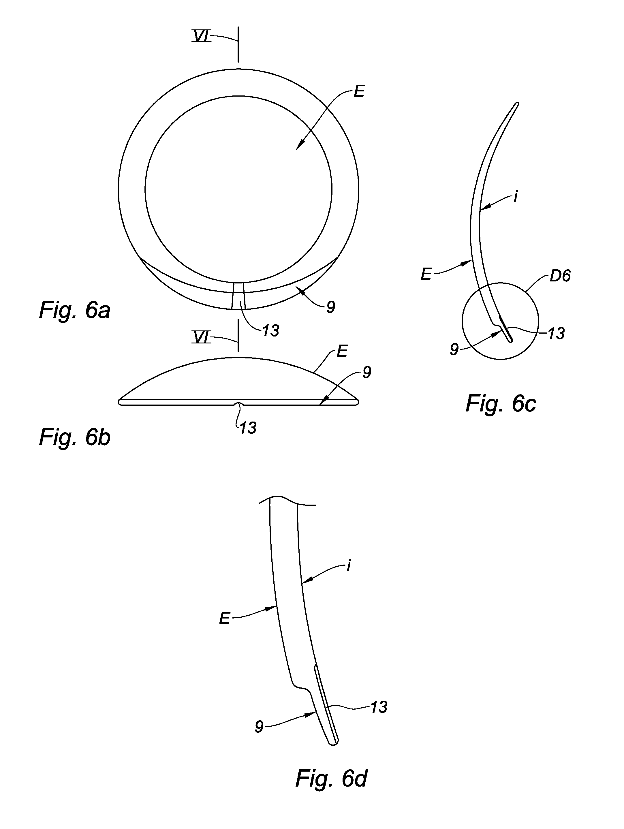
[0043]“Inner face” indicates the concave face i of the lens designed to be applied to the eye, and “outer face” indicates the other face E of the lens.

[0044]As can be seen in FIG. 3, the edge 5 of the lens according to the invention has a generally circular shape.

[0045]The circle defined by this edge may typically have a diameter of between 8 an...


PUM


Abstract

A contact lens includes at least two focal lengths, a single lower bearing surface capable of allowing the lens to be translated relative to an eye, and an area placed in the lower portion of the lens, the area having an outer face connected to a remainder of the outer face of the lens via a recess and the area having an inner face indistinguishable from the rest of an inner face of the lens, where the recess defines the lower bearing surface, and where the area is thin with an average thickness of the same order of magnitude as a thickness of an upper edge of said lens.

Description

CROSS REFERENCE TO RELATED APPLICATIONS[0001]This application is a continuation of International Patent Application No. PCT / FR2008 / 001125 filed on 28 Jul. 2008 which claims priority to French Patent Application Number 07 / 06572 filed on 19 Sep. 2007, both of which said applications are herein incorporated by reference in their entirety.TECHNICAL FIELD[0002]The present invention relates to contact lenses and may be used for various types of lenses that have to translate upward and / or stabilize.BACKGROUND[0003]The principle of stabilizing contact lenses with lower bearing surface, such as that which is shown in FIGS. 1 and 2 appended hereto, is known.[0004]“Lower bearing surface” indicates that the lower edge 1 is sufficiently thick to butt against the edge of the lower eyelid, without passing beneath, unlike the upper edge 3 which, for its part, is “thin”, that is to say suitable for passing beneath the upper eyelid.[0005]Because of the abutment of the lower edge of the lens on the ed...

Claims


Application Information

Patent Timeline
IPC IPC(8): G02C7/04G02C7/06
CPCG02C7/048G02C7/04
Inventor PERRIN, GERARD
Owner LAB PRECILENS
Why Eureka
Try Eureka