Programmable Light Source

Inactive Publication Date: 2010-07-08
KANADE UDAYAN +1
View PDF6 Cites 2 Cited by
  • Summary
  • Abstract
  • Description
  • Claims
  • Application Information

AI Technical Summary

Benefits of technology

[0006]The above and other preferred features, including various details of implementation and combination of elements are more particularly described with reference to the accompanying drawings and pointed out in the claims. It will be understood that the particular methods and sys

Problems solved by technology

Such systems suffer from a limited range of producible spectra.
These systems too suffer from a limited range of producible spectra.
Thus, it will fail to simulate the natural light source.

Method used


Image

  • Programmable Light Source
  • Programmable Light Source
  • Programmable Light Source

Examples


embodiments

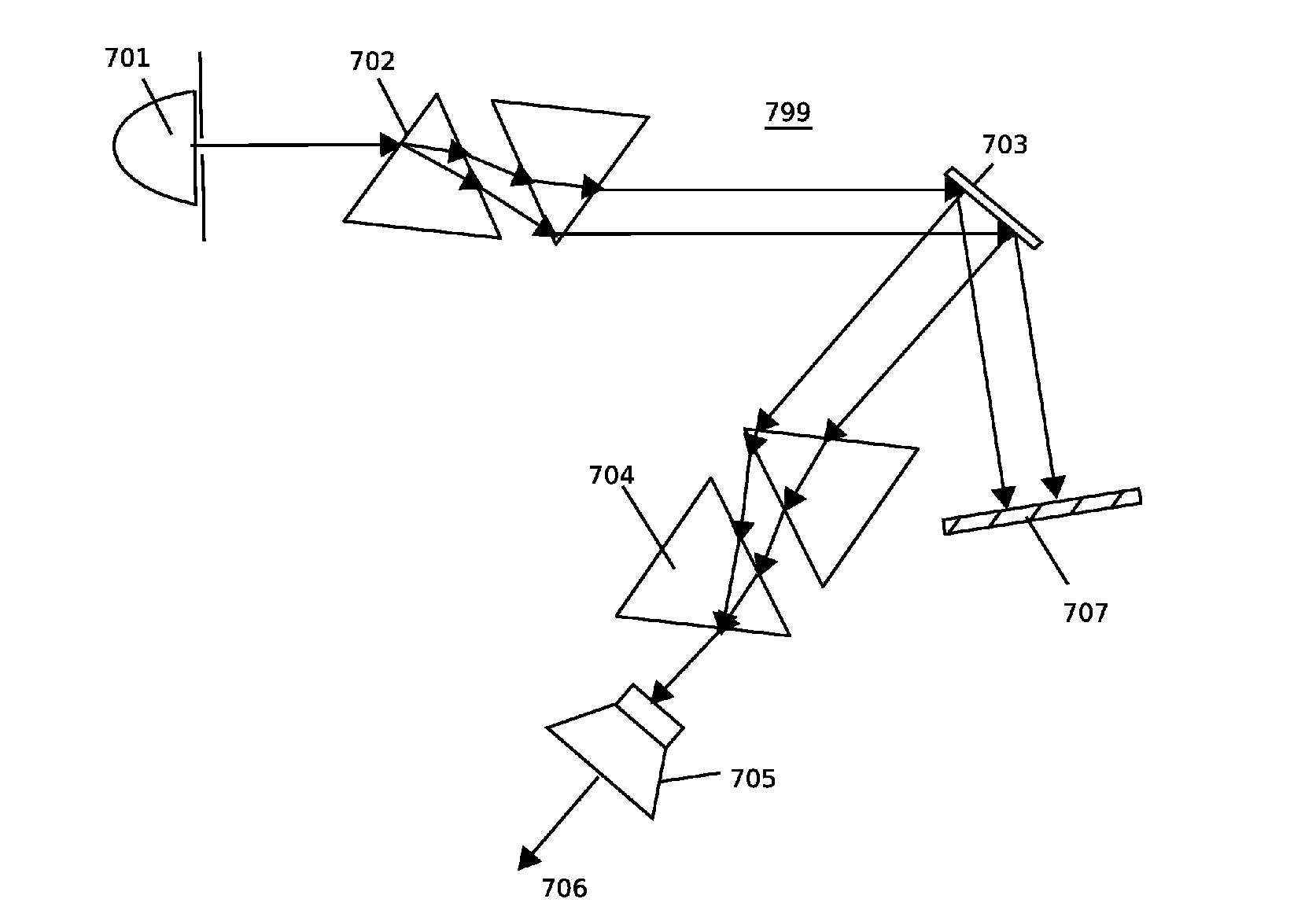
[0045]FIG. 7 illustrates a block diagram of an exemplary programmable light source 799 comprising a micromirror device as light modulator, a parallel prism apparatus for spectrum separation and a parallel prism apparatus for light recombination according to an embodiment of the present invention. A beam of light from the light source 701 is directed onto a parallel prism apparatus 702. The beam of light from 701 is separated into its spectral components by the parallel prism apparatus 702. A light beam comprising separated spectral components is incident on a micromirror device 703 which is used as a spectrum shaping device as explained above. The micromirror device modulates the intensity of each spectral component by switching columns of mirrors. In one state of a column, the corresponding spectral component is reflected towards the light recombination apparatus 704. In another state, the spectral component is reflected onto a light absorber 707 which absorbs it. In this manner, t...


PUM


Abstract

A programmable spectrum light source is disclosed. In one embodiment, the programmable light source comprises a light source, a spectrum separation system that splits the light into its constituent spectral components, a light modulator that modulates the spectral components according to a required spectral envelope and a light recombination system that recombines the shaped spectral components to produce light with a required spectrum.

Description

[0001]This patent claims priority from provisional patent no. 1059 / MUM / 2007 titled “A programmable light source” filed in Mumbai, India on 5 Jun. 2007.TECHNICAL FIELD[0002]The present invention relates to a programmable light source. More particularly, the present invention relates to a light source whose spectrum can be programmed as required.BACKGROUND ART[0003]Light sources that can change the spectrum of light emitted by them find uses in theater, movie, photography, architectural lighting and other industries and home appliances. Many prior art systems work as light sources with programmable spectra. For example, some systems use a set of changeable color filters in front of a light source. Such systems suffer from a limited range of producible spectra. Other systems use a set of light sources of different colors (such as red, green and blue). These systems too suffer from a limited range of producible spectra. Even though bounced off a white object, this range of spectra cover...

Claims


Application Information

Patent Timeline
IPC IPC(8): G02B26/00G02B5/04F21V9/40
CPCG02B26/0833G02B27/1006G02B27/1086G02B27/126G02B27/14H04N9/3158
Inventor KANADE, UDAYANJOSHI, MANOHAR
Owner KANADE UDAYAN
Why Eureka
Try Eureka