Method for uniform application of fluid into a reactive reagent area

a technology of reactive reagents and fluids, applied in the field of microfluidic devices, can solve the problems of inability to uniformly distribute samples over the reagent region, difficult to obtain desired performance, and small sample sizes, etc., and achieve accurate and repeatable assays

Inactive Publication Date: 2010-07-08
PUGIA MICHAEL J +5
View PDF72 Cites 11 Cited by
  • Summary
  • Abstract
  • Description
  • Claims
  • Application Information

AI Technical Summary

Benefits of technology

[0017]The invention relates in particular to the use in a microfluidic device of microstructures adapted to uniformly distribute small samples of 10 μL or less over reagents disposed on a substrate, thereby making possible accurate and repeatable assays of the analytes of interest in such samples.

Problems solved by technology

However, smaller samples introduce difficult problems.
Whether or not such devices provided accurate and repeatable results, it has been found that as the size of the sample to be analyzed becomes very small, say below about 2 μL, obtaining the desired performance becomes more and more difficult.
However, there is no attempt made to uniformly distribute the sample over the reagent region.
Kellogg et al, U.S. Pat. No. 6,063,589, contains an extended discussion of microfluidic devices for analysis of small samples but does not address the problems relating to assuring that a sample fluid is uniformly distributed over a reagent area.
No means is provided to assure that the sample is uniformly distributed over the reagent area.

Method used


Image

  • Method for uniform application of fluid into a reactive reagent area
  • Method for uniform application of fluid into a reactive reagent area
  • Method for uniform application of fluid into a reactive reagent area

Examples


example 1

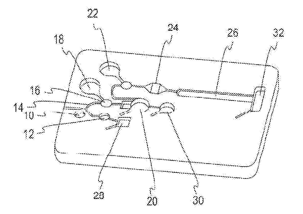
[0055]In this example, a test for HbA1c is carried out in a microfluidic chip of the type shown in FIG. 1. A sample of blood is introduced via sample port 10, from which it proceeds by capillary action to the pre-chamber 12 and then to metering capillary 14. The auxiliary metering well 16 is optional, only being provided where the sample size requires additional volume. The denaturant / oxidizing liquid is contained in well 18. Mixing chamber 20 provides space for the blood sample and the denaturant / oxidant well 22 contains a wash solution. Chamber 24 provides uniform contact of the preconditioned sample with labeled monoclonal antibodies disposed on a dry substrate. Contact of the labeled sample with the agglutinator, which is disposed on a substrate is carried out in chamber 26, producing a color which is measured to determine the amount of glycated hemoglobin in the sample. The remaining wells provide space for excess sample 28, excess denatured sample 30, and for a wicking materia...

example 2

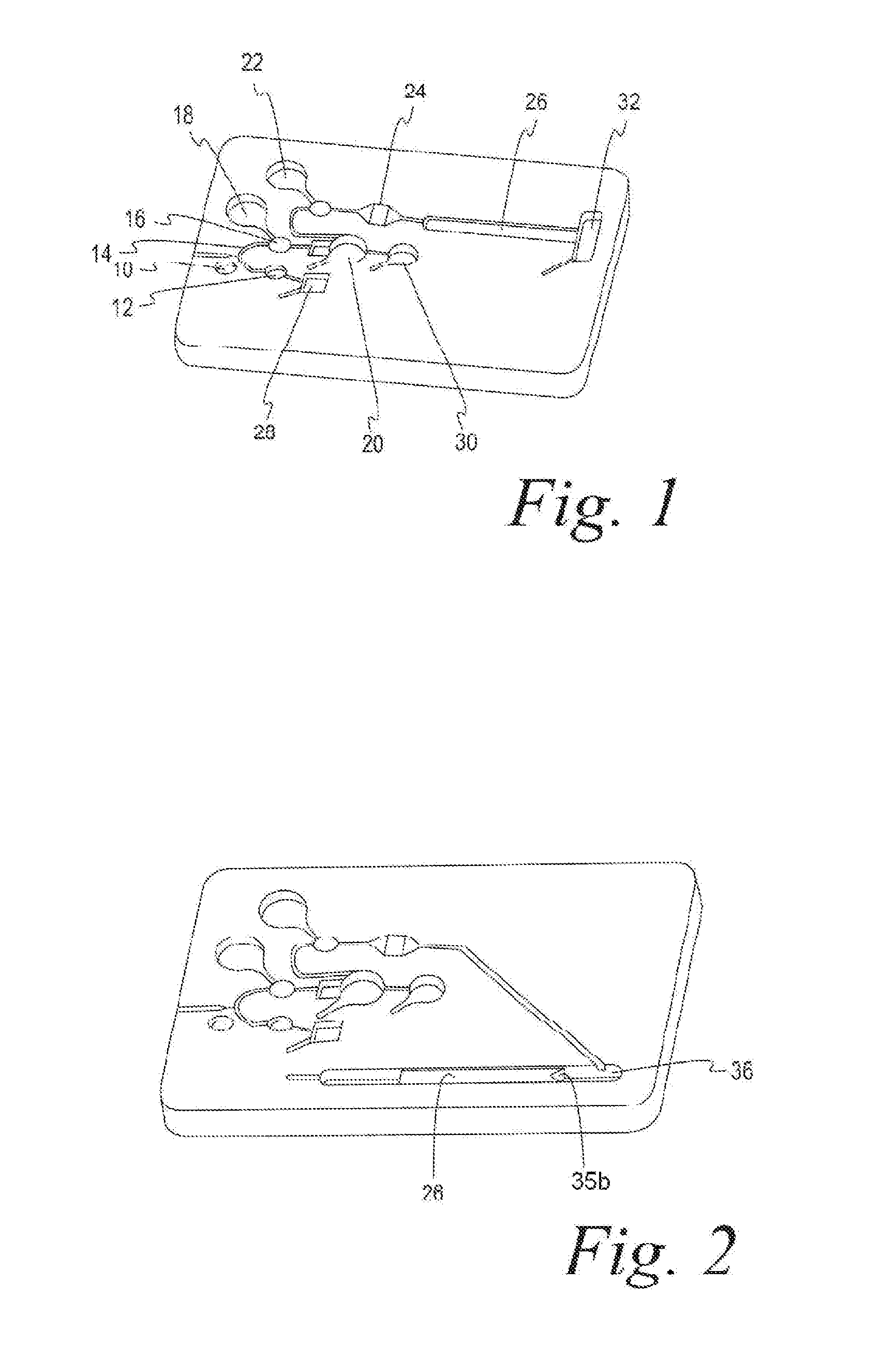
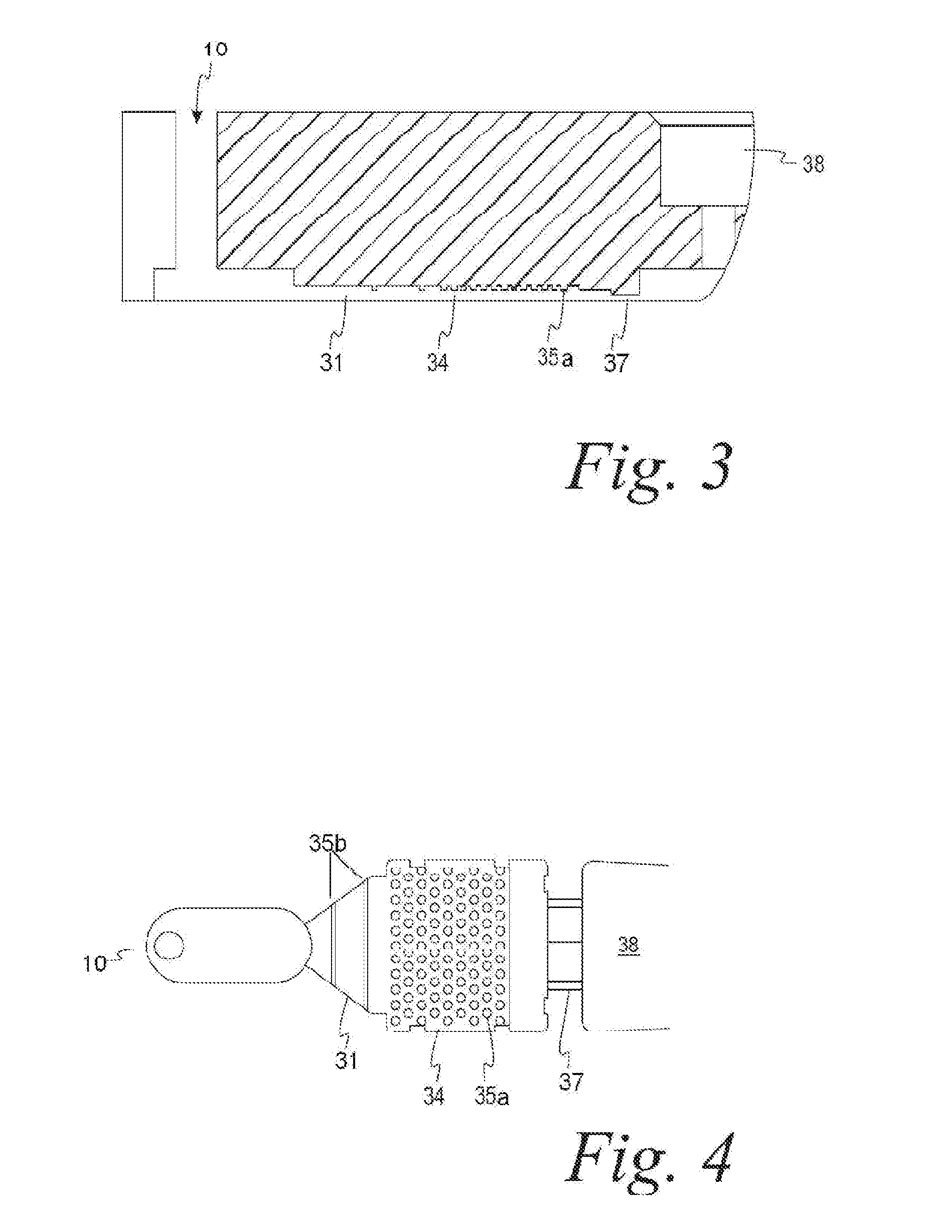
[0058]The test described in Example 1 was repeated, using the modified microfluidic chip shown in FIG. 2. In FIG. 2, the agglutinator chamber 26 was positioned so that the labeled sample flowed “uphill”, i.e. toward the center of rotation, assisted by the wicking action of absorbent material placed at the uphill end of the strip. Equivalent results were obtained. In this case, the microstructure that directs the flow is a ramp 35b leading upward to a plateau onto which the nitrocellulose reagent is placed. In an alternative embodiment, the strip would extend into the pre-chamber 36 which contains the sample liquid.

example 3

[0059]The test of Example 1 is repeated with a microfluidic chip in which the labeled sample entered at the center of the agglutination strip 26 so that the labeled sample wicks in two directions.


PUM

PropertyMeasurementUnit
widthsaaaaaaaaaa
widthsaaaaaaaaaa
diametersaaaaaaaaaa

Abstract

Analytical results obtained with microfluidic devices are improved by providing structural features in areas containing dry supported reagents, the structural features directing the flow of a sample over the area in a predetermined uniform manner and facilitating the purging of air.

Description

[0001]This application claims benefit of patent application U.S. Ser. No. 10 / 608,400 filed Jun. 27, 2003.BACKGROUND OF THE INVENTION[0002]This invention relates to microfluidic devices, particularly those that are used for analysis of biological samples. Such devices are intended to accept very small samples of blood, urine, and the like. The samples are brought into contact with reagents capable of indicating the presence and quantity of analytes found in the sample. Microfluidic devices are intended to be used for rapid analysis, thus avoiding the delay inherent in sending a biological sample to a central laboratory.[0003]Many devices have been suggested for analysis near the patient, some of which will be discussed below. In general, such devices use only small samples, typically 0.1 to 200 μL. With the development of microfluidic devices the samples required have become smaller typically about 0.1 to 20 μL, which is a desirable aspect of their use. However, smaller samples intro...

Claims


Application Information

Patent Timeline
Patent Type & Authority Applications(United States)
IPC IPC(8): G01N30/00G01N33/487B01L3/00G01NG01N1/10G01N15/06G01N21/00G01N33/00G01N33/48
CPCB01L3/502723B01L3/502746B01L2200/0684B01L2200/16B01L2300/0816Y10T436/2575B01L2400/0409B01L2400/0418B01L2400/0487B01L2400/0688B01L2400/086B01L2400/0406
Inventor PUGIA, MICHAEL J.PROFITT, JAMES A.KUO, HAI-HANGBLANKENSTEIN, GERTPETERS, RALF-PETERSCHULMAN, LLOYD S.
Owner PUGIA MICHAEL J
Why Eureka
Try Eureka