
Sample analysis system and method of use

a sample analysis and sample technology, applied in the field of patient sample collection and analysis system, can solve the problems of increasing the cost associated with the development and manufacture of the analysis instrument family, increasing the cost of conventional analysis instrument use, and requiring a significant amount of manual labor to operate, so as to achieve accurate and repeatable assays, uniform distribution of fluid samples, and air venting

Inactive Publication Date: 2013-02-14
SIEMENS HEALTHCARE DIAGNOSTICS INC
View PDF4 Cites 43 Cited by
  • Summary
  • Abstract
  • Description
  • Claims
  • Application Information

AI Technical Summary

Benefits of technology

This patent is about devices that can analyze small samples of fluid. The devices have a special chamber that allows for accurate and repeatable analysis of the fluid's analytes. The sample is entered through a small opening and air is purged from the system without trapping any air bubbles. This design ensures a uniform distribution of the sample and allows for the safe release of air. The devices use microfluidic technology, which allows for the analysis of small samples of fluid.

Problems solved by technology

This increases the costs associated with the development and manufacture of the family of analysis instruments.
The use of conventional analysis instruments is also labor intensive.
In particular, the conventional urinalysis instruments including the automated machines still require a significant amount of manual labor to operate.
However, smaller samples introduce difficult problems.
As the sample is moved into a well or chamber for immediate or later reaction, it is important that the liquid is uniformly distributed such that all the air in the well is expelled, since air will adversely affect the movement of liquid and the analytical results.
Also, there are other problems associated with the initial introduction of the sample to the microfluidic device.
A small amount of liquid must be deposited under conditions which force air out, but leave the sample in the inlet port and not on the surface of the device because specimens on the surface may cause carry-over and contamination between different samples.
Air in the port may cause under-filling and, consequently, under estimation of the analytical results.
Air bubbles in the inlet port or the receiving inlet chamber might interfere with the further liquid handling, especially if lateral capillary flow is used for further flow propulsion.
If the vent passage is blocked by liquid before all of the well air has escaped, air bubbles will form in the well and reduce the accuracy of the test.
If the well is under-filled due to the presence of air bubbles then the measurements are affected because less liquid is available for the analysis.
If the well is over-filled, excess liquid may enter the downstream micro fluidic circuit and interfere with the processing of the correct sample volume.
Previous systems have often suffered from the inability to induce and cause accurate fluid flows within the device.
Rising healthcare costs are causing diagnostics suppliers to seek process improvements which reduce the cost to deliver high quality clinical information.
Blood collection tubes and urine cup processes account for substantial labor and materials in the total cost of delivering a diagnostic result.
First, molding of μm fluidic (microfluidic) patterns into plastics allows miniaturization of the reagent amounts and produces smaller and low cost disposables for diagnostics. These microfluidic patterns allow liquid and dry reagents to be combined to produce lab quality results conveniently in a POC testing setting. Microfluidics also reduces the amounts of expensive reagent biochemicals used. This is important as biochemicals are essential for use in affinity capture; a fluidic process of passing liquid through a binding area to amplify binding of the biochemical to the analyte of interest. This amount of analyte bound is measured by use of labels, such as enzyme labels, to further amplify and produce a detectable signal.
Second, miniaturized optical designs (micro-optics or MORH) using μm-sized LEDs, μm-sized photodiodes and light guides are capable of reading mm-sized reagent areas in the microfluidic disposables. These micro-optic designs allow smaller and lower cost instruments.
Third, delivery of miniaturized volumes of liquid reagents (pL to μL) has been achieved using μm-sized nozzles. These nozzles are opened on demand by piezo-ceramic electronics, for example, allowing μsec timing of liquid additions. Since these nozzles release droplets from a distance, the liquid reagent can be separated and not directly contact the microfluidic disposable. This improves storage stability and allows liquids to be held in reservoirs used many times over longer periods.
Fourth, micro-volumes of sample are a sensitivity and detection challenge. A minimum sensitivity of 10−12 to 10−13 M is needed for immunoassay and nucleic acid analysis. High sensitivity electromechanical analyzers miniaturized to small areas (e.g., 1-10 mm2) must be capable of measuring small volumes (e.g., 0.1-20 μL). Nanometer electrode patterns are effective but cost effective fabrication and scale up of are required. Fabrication and scale up of detection can be achieved with Complementary metal-oxide-semiconductor (CMOS) technology for example.
However, there are problems in most effectively and efficiently combining all of these elements in a simple system.

Method used


Image

  • Sample analysis system and method of use
  • Sample analysis system and method of use
  • Sample analysis system and method of use

Examples


Embodiment Construction

[0076]The description herein of several embodiments describes non-limiting examples that further illustrate the presently claimed and disclosed inventive concept(s).

[0077]In the following detailed description, numerous specific details are set forth in order to provide a more thorough understanding of the disclosure. However, it will be apparent to a person having ordinary skill in the art that the presently claimed and disclosed inventive concept(s) may be practiced without these specific details. In other instances, features which are well known to persons of ordinary skill in the art have not been described in detail to avoid complication unnecessarily the description.

[0078]Therefore, unless defined otherwise, all technical and scientific terms used herein have the same meanings as commonly understood by one skilled in the art to which the presently claimed and disclosed inventive concept(s) pertains. For example, the term “plurality” refers to “two or more.” The singular forms “...


PUM

PropertyMeasurementUnit
diameteraaaaaaaaaa
diameteraaaaaaaaaa
volumesaaaaaaaaaa

Abstract

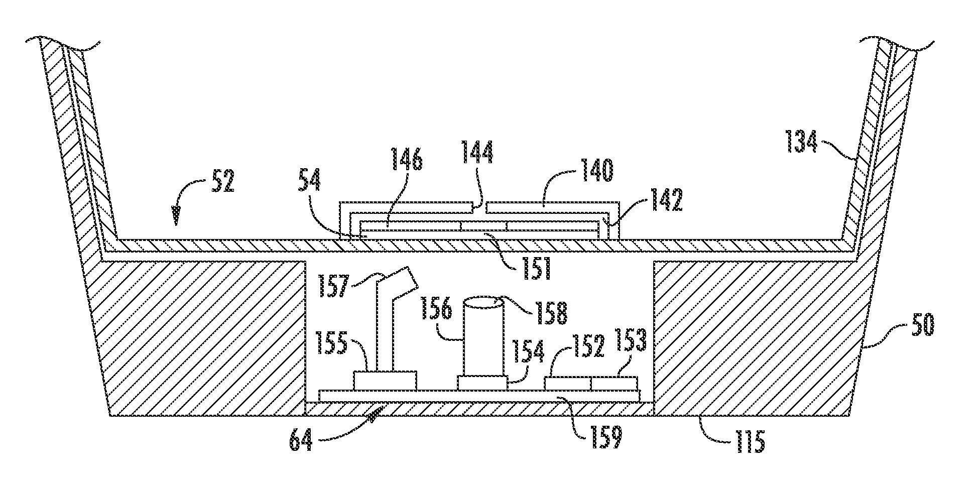
A sample collection device having a sample container and microfluidic device having one or more microfluidic circuits, the system for analyzing biological samples. The microfluidic device has a sample inlet port, a microconduit in communication with the inlet port and with reaction chamber. The reaction chamber is connected to an air vent via another microconduit. Air may be vented from the microfluidic circuit via the air vent of the microfluidic circuit via an air vent in the sample container.

Description

CROSS-REFERENCE TO RELATED APPLICATIONS[0001]Not applicable.STATEMENT REGARDING FEDERALLY SPONSORED RESEARCH OR DEVELOPMENT[0002]Not applicable.BACKGROUND[0003]1. Field of the Presently Disclosed and Claimed Inventive Concept(s)[0004]The presently disclosed and claimed inventive concept(s) relates to a system for collecting and analyzing patient samples. In particular, the presently disclosed and claimed inventive concept(s) provides an improved sample analysis system and method that greatly reduces the labor and the likelihood of errors involved in collecting and analyzing patient samples. The presently disclosed and claimed inventive concept(s) also relates to sample analysis systems which include microfluidic devices, particularly those that are used for analysis of biological samples.[0005]2. Background of the Presently Disclosed and Claimed Inventive Concept(s)[0006]Various types of analytical tests related to patient diagnosis and therapy can be performed by analysis of a liqu...

Claims


Application Information

Patent Timeline
Patent Type & Authority Applications(United States)
IPC IPC(8): A61B5/20G01N33/53G01N33/48B23P17/04
CPCA61B10/0045Y10T29/49826A61B10/007B01L2200/025B01L2300/0654B01L2400/0457B01L3/502707B01L2300/0851B01L3/5027B01L3/508B01L2200/0621B01L2300/0832B01L2400/0406B01L2200/027B01L2300/0816
Inventor PUGIA, MICHAEL J.PANEBIANCO, GREGORY PAULLU, HENRY
Owner SIEMENS HEALTHCARE DIAGNOSTICS INC
Learn More