
Electromagnetic slurry magnetic separator

A technology of magnetic separator and slurry, which is applied in magnetic separation, solid separation, chemical instruments and methods, etc. It can solve the problems of large number of sets required for capacity expansion, influence on the purity of concentrate, uneven distribution of fluid, etc., and achieve distribution Uniformity, high concentrate grade and purity, small footprint

Pending Publication Date: 2019-01-04
SHANDONG HUATE MAGNET TECH
View PDF6 Cites 0 Cited by
  • Summary
  • Abstract
  • Description
  • Claims
  • Application Information

AI Technical Summary

Problems solved by technology

[0003] The existing electromagnetic slurry magnetic separator generally adopts a common pipeline channel for slurry and flushing water, which makes the fluid distribution uneven and the slag discharge incomplete, which reduces the concentrate grade and affects the purity of the concentrate
In addition, the diameter of the sorting chamber is small, the output of a single unit is low, and the number of units required for capacity expansion has the disadvantages of large energy consumption and large space occupation.

Method used


Image

  • Electromagnetic slurry magnetic separator
  • Electromagnetic slurry magnetic separator
  • Electromagnetic slurry magnetic separator

Examples


Embodiment Construction

[0025] The present invention will be described in further detail below in conjunction with the accompanying drawings and embodiments.

[0026] For ease of description, in the present invention, fluid flow from top to bottom is defined as the "forward" direction, and fluid flow from bottom to top is defined as the "reverse" direction. Among them, the term "communication" should be understood in a broad sense, and it can be that two elements are directly connected or indirectly connected through an intermediary. For those of ordinary skill in the art, the meaning of this term can be understood according to the specific situation. Concrete meaning.

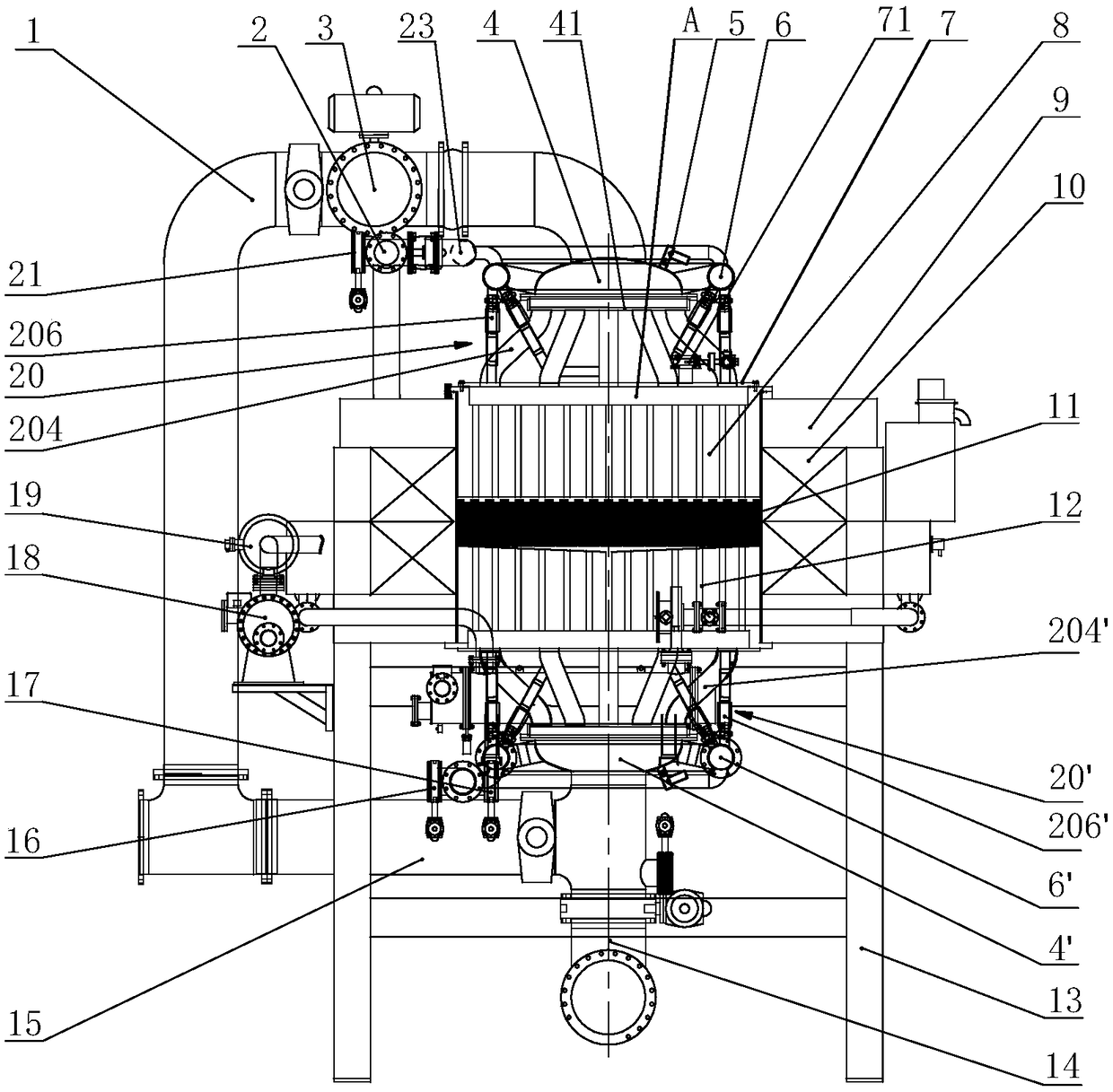
[0027] The electromagnetic slurry magnetic separator of the present invention includes a magnetic separation device, a flow diversion device, a flow confluence device and a cooling device arranged on the frame 13 .

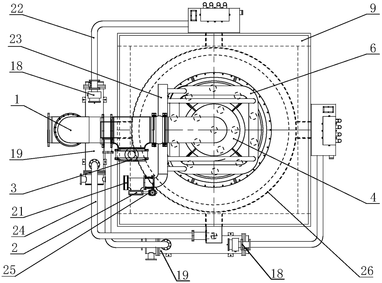
[0028] Such as figure 1 and figure 2 As shown, wherein, the magnetic separation device includes: a coil 10 arrange...


PUM


Abstract

The invention discloses an electromagnetic slurry magnetic separator. The electromagnetic slurry magnetic separator comprises a magnetic separation device, a splitting device, a converging device anda cooling device. The magnetic separation device comprises a coil arranged in a wire box, and an upper magnetic pole, a magnetic medium device and a lower magnetic pole communicated with one another to form a magnetic separation cavity are arranged in an air gap in the middle of the coil; the splitting device is arranged above the upper magnetic pole and comprises a multi-pipeline splitting interface, a splitter and a water separator; the multi-pipeline splitting interface comprises a plurality of splitting pipes communicated with the splitter and the magnetic separation cavity and a pluralityof water dividing pipes communicated with the water separator and the magnetic separation cavity; the converging device is arranged below the lower magnetic pole, is substantially as same as the splitting device in structure, and the two are symmetrical; and the cooling device adopts a forced oil circular cooling mode. According to the electromagnetic slurry magnetic separator, a pipeline channelwhere slurry and flushing water are separated, a flow is distributed uniformly, the concentrate grade and purity are high, and waste of the slurry is small; the cooling effect of the coil is good, the diameter of the coil is great, the exciting power is small, the ton energy consumption is low, the output is high and the occupied area is small.

Description

technical field [0001] The invention relates to the technical field of magnetic separation equipment, in particular to a large-scale electromagnetic slurry magnetic separator. Background technique [0002] For non-metallic minerals, iron and other magnetic impurities will affect the quality of minerals, such as: whiteness, concentrate rate, purity, etc. of kaolin. Therefore, the ability of magnetic separation equipment to remove ferromagnetic impurities has a direct impact on the quality of non-metallic minerals. With the increasing demand for high-end non-metallic mines, there is an urgent need for large-scale electromagnetic slurry magnetic separators. [0003] The existing electromagnetic slurry magnetic separator generally adopts a common pipeline channel for slurry and flushing water, which makes the fluid distribution uneven, the slag discharge is not thorough, the concentrate grade is reduced, and the purity of the concentrate is affected. Moreover, the diameter of ...

Claims


Application Information

Patent Timeline
Patent Type & Authority Applications(China)
IPC IPC(8): B03C1/02
CPCB03C1/02
Inventor 王兆连丁长田贾洪利刘风亮王宝春陈传君王娟娟
Owner SHANDONG HUATE MAGNET TECH
Learn More