
Low ground resistance golf tee

a golf tee and low ground technology, applied in the field of low ground resistance golf tees, can solve the problems of many wooden golf tees having a tendency to break, wooden golf tees being particularly difficult to insert into firm playing surfaces, and dry playing surfaces, etc., to achieve low ground resistance, low ground resistance, and low ground resistance

Inactive Publication Date: 2010-07-08
SCHNEIDER MARK ALLEN
View PDF33 Cites 6 Cited by
  • Summary
  • Abstract
  • Description
  • Claims
  • Application Information

AI Technical Summary

Benefits of technology

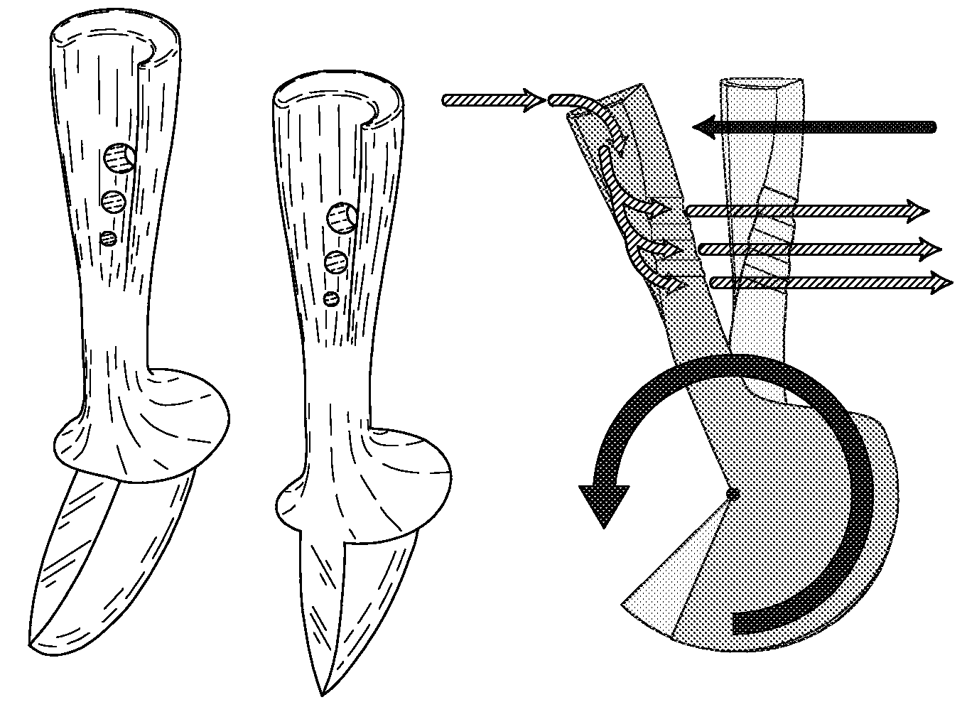
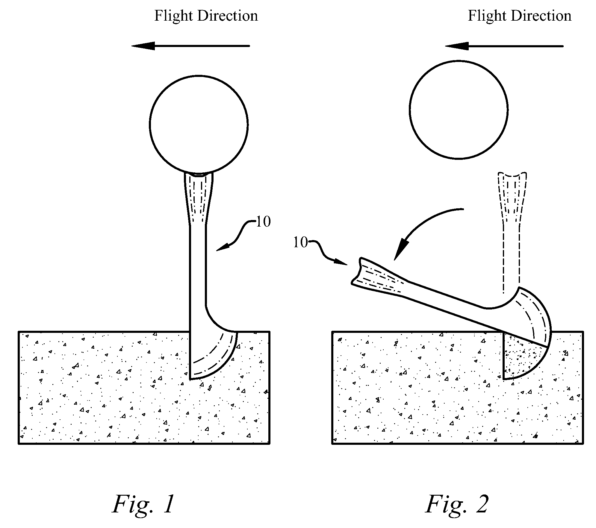
[0007]The present invention is a low ground resistance golf tee for insertion into a playing surface to support a golf ball to be struck by a golf club launching the golf ball in a flight direction. The low ground resistance golf tee is designed to pivot forward in the flight direction with minimal resistance when struck by the golf club, or when the golf ball is struck by the golf club, while still providing a stable platform for elevating the golf ball above the playing surface. The low ground resistance golf tee is also designed to minimize the final distance that the low ground resistance golf tee comes to rest from the initial teeing location.

Problems solved by technology

First, conventional wooden golf tees have a tendency to break upon impact by a golf club.
Second, wooden golf tees can be particularly difficult to insert into firm, dry playing surfaces.
In fact, many wooden golf tees have a tendency to break when trying to insert them into firm, dry playing surfaces.
Third, conventional wooden golf tees, due to their mass being concentrated towards the ball supporting end, have a tendency to fly relatively far away from the original teeing location.
Prior art golf tees have failed to account for all of these drawbacks.

Method used


Image

  • Low ground resistance golf tee
  • Low ground resistance golf tee
  • Low ground resistance golf tee

Examples


Embodiment Construction

[0080]The present invention includes a low ground resistance golf tee (10). The invention enables a significant advance in the state of the art. The preferred embodiments of the apparatus accomplish this by new and novel methods that are configured in unique and novel ways and which demonstrate previously unavailable but preferred and desirable capabilities. The description set forth below in connection with the drawings is intended merely as a description of the presently preferred embodiments of the invention, and is not intended to represent the only form in which the present invention may be constructed or utilized. The description sets forth the designs, functions, means, and methods of implementing the invention in connection with the illustrated embodiments. It is to be understood, however, that the same or equivalent functions and features may be accomplished by different embodiments that are also intended to be encompassed within the spirit and scope of the invention.

[0081]...


PUM


Abstract

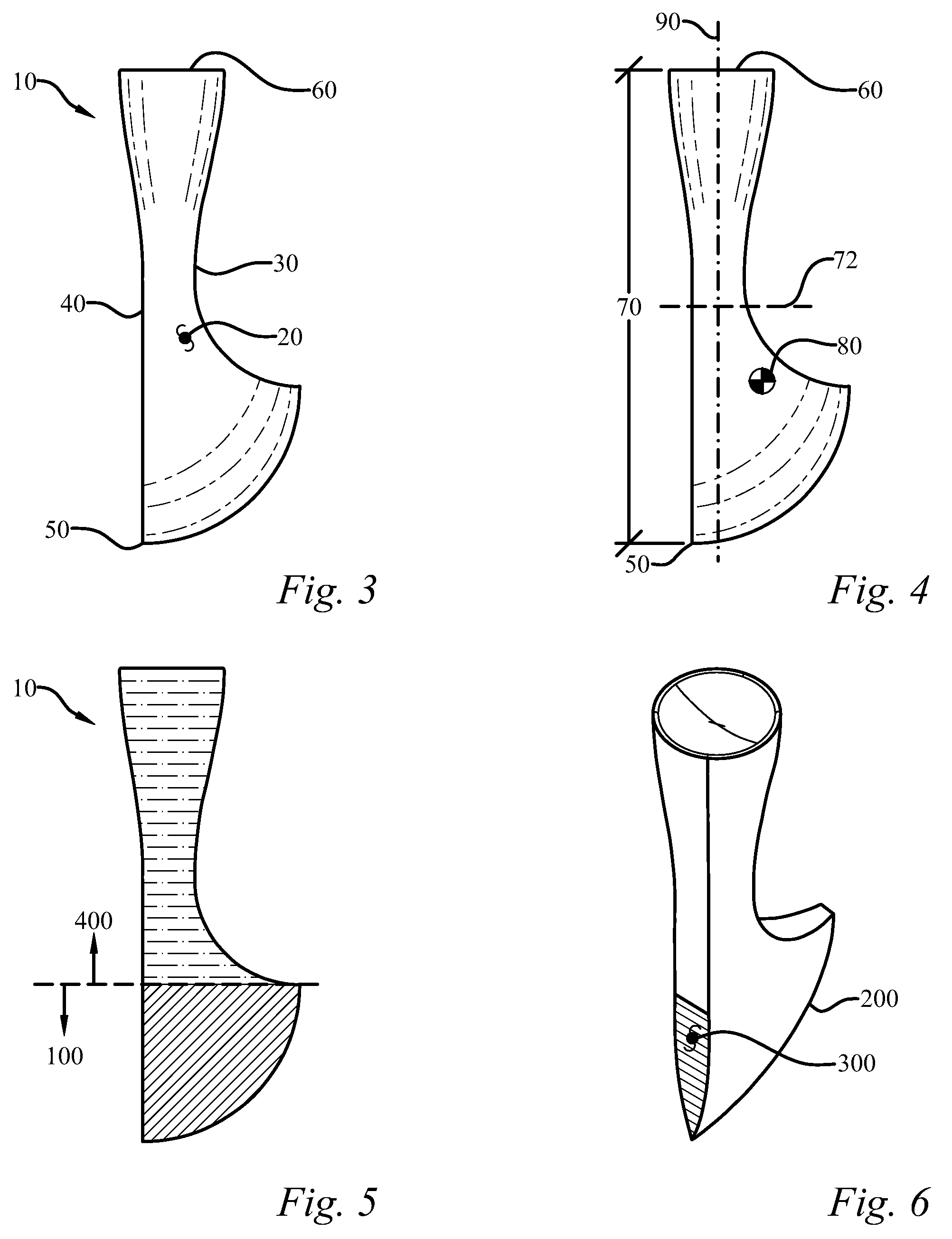
A low ground resistance golf tee for insertion into a playing surface to support a golf ball above the playing surface to be struck by a golf club launching the golf ball in a flight direction is provided. The golf tee includes a body having an impact side, a release side, an insertion end, and a ball support end. The golf tee has a low exit resistance region that includes a low exit resistance region insertion edge for penetrating and separating the playing surface to create a preferred exit path for the low exit resistance region upon impact by the golf club. The golf tee further includes a stem region located between the low exit resistance region and the ball support end, which is designed to be displayed above the playing surface. Upon impact, the golf tee pivots forward in the flight direction with minimal resistance from the playing surface.

Description

CROSS-REFERENCE TO RELATED APPLICATIONS[0001]This application claims the benefit of U.S. provisional patent application Ser. No. 61 / 020,855, filed on Jan. 14, 2008, all of which is incorporated by reference as if completely written herein.TECHNICAL FIELD[0002]The present invention relates to sports equipment, and more particularly to a low ground resistance golf tee for insertion into a playing surface to support a golf ball to be struck by a golf club.BACKGROUND OF THE INVENTION[0003]Golf tees are an often overlooked piece of equipment in the game of golf. Many golfers think of golf tees as simply a device for elevating a golf ball above a playing surface without giving any thought to the effect that a golf tee has on the flight of the golf ball. This fact explains why today's golfers still use the same wooden golf tee utilized by golfers of decades past.[0004]Conventional wooden golf tees have several drawbacks. First, conventional wooden golf tees have a tendency to break upon im...

Claims


Application Information

Patent Timeline
Patent Type & Authority Applications(United States)
IPC IPC(8): A63B57/00
CPCA63B57/0018A63B57/10A63B57/19
Inventor SCHNEIDER, MARK ALLEN
Owner SCHNEIDER MARK ALLEN
Learn More