Electrical connector

a technology of electrical connectors and connectors, applied in the direction of coupling device connections, electrical apparatus, coupling protection earth/shielding arrangements, etc., can solve the problems of insufficient electromagnetic-wave shut-off function, complex configuration, laborious turning operations of both members, etc., to achieve good shielding performance, reduce ground resistance, and efficient assembly performance

Inactive Publication Date: 2015-10-29
DAIICHI SEIKO CO LTD
View PDF13 Cites 5 Cited by
  • Summary
  • Abstract
  • Description
  • Claims
  • Application Information

AI Technical Summary

Benefits of technology

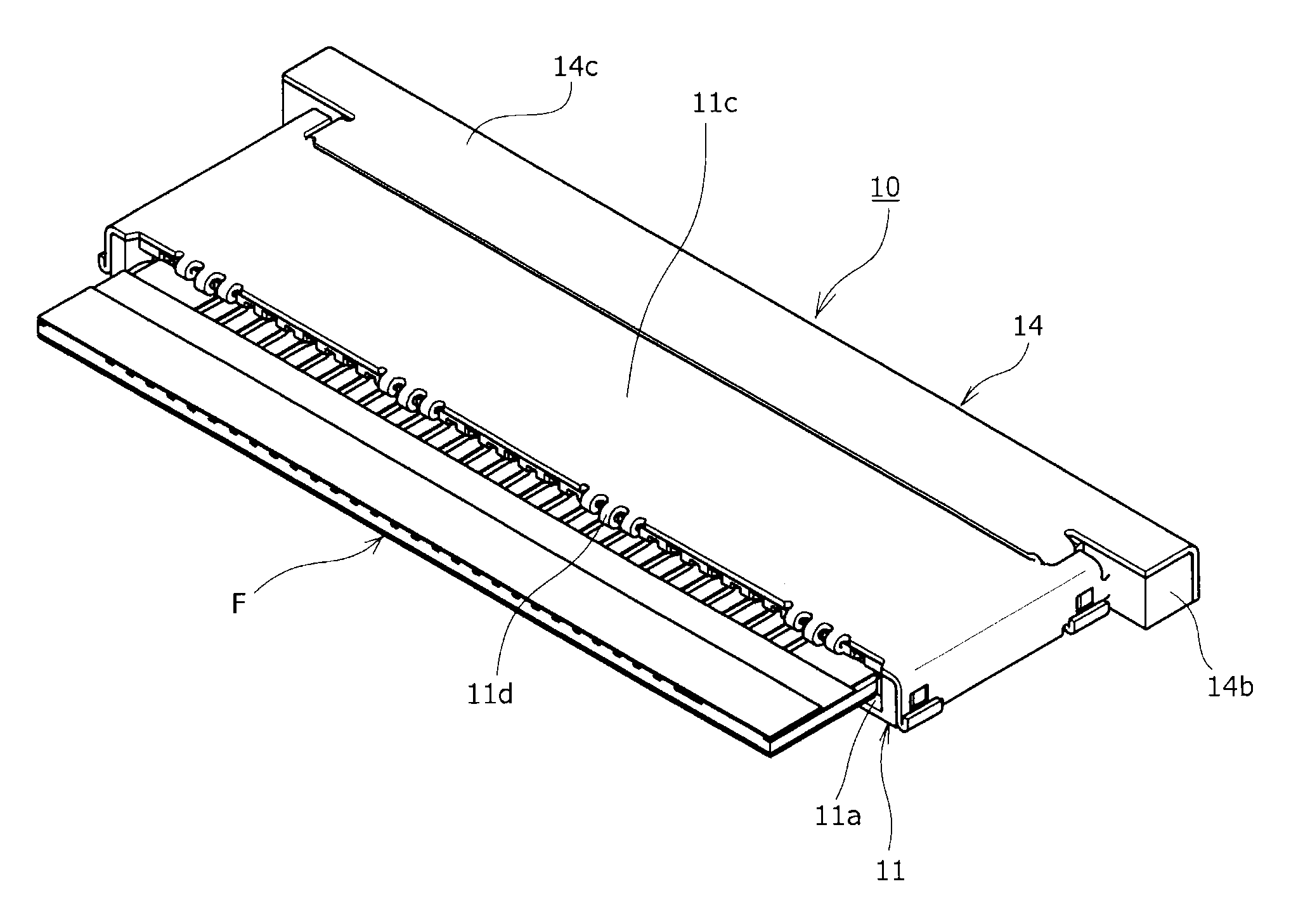
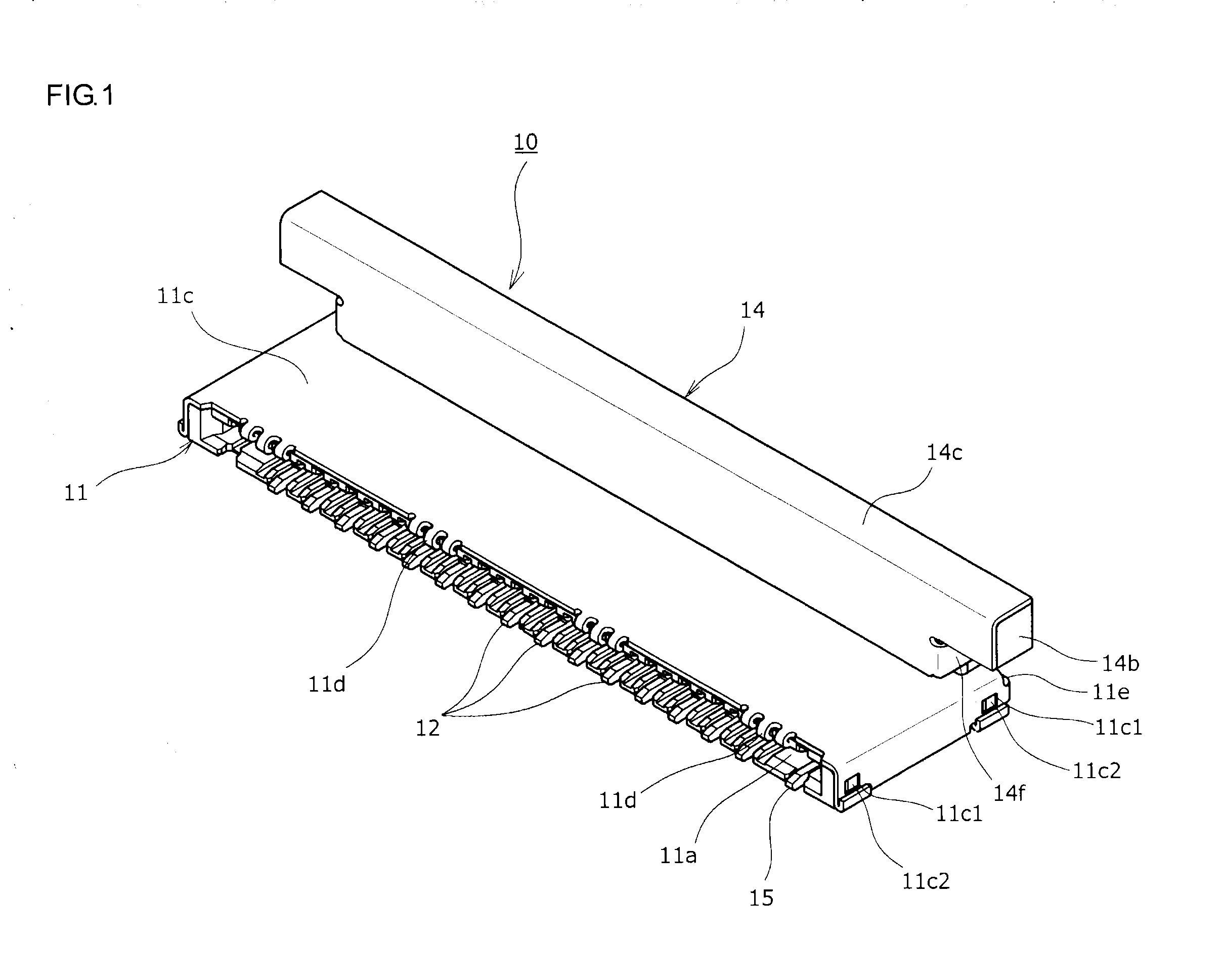
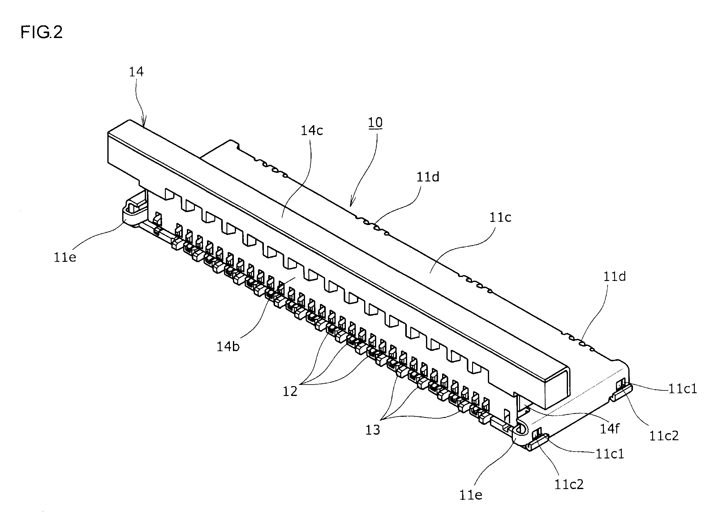
The present invention provides an electrical connector that can efficiently shield transmission paths from signal transmission to printed wiring boards. The simple and cost-effective design allows for easy assembly and improves operability and reliability. The actuator-side shield shell and insulating-housing-side shield shell contact each other without a gap, resulting in improved electromagnetic-wave shut-off performance. Ground characteristics are improved by reducing ground resistance, and the ground circuit is in a multi-point contact state, reducing ground resistance. The actuator-side shield shell covers the insulating housing and the actuator, continuously covering the transmission paths. The invention provides good shielding performance with efficient assembly performance and improved reliability.

Problems solved by technology

However, in an electrical connector provided with an actuator, the actuator is turned or slid; therefore, a spatial part is formed between the insulating housing and the actuator, and there is a problem that a sufficient electromagnetic-wave shut-off function cannot be easily obtained.
However, in such a conventional electrical connector, although a predetermined action of electromagnetic-wave shut-off is obtained, there are problems that the configuration is complex and that the turning operations of both of the members takes labor since the mechanism of turnably supporting both of the actuator and the shield shells is employed.
Moreover, for example if the electrical connector is suctioned from the upper side, for example, in an assembly process of the electrical connector, there is a problem that the shield shell covering the upper surface of the insulating housing is disturbing, and efficient assembly performance cannot be easily obtained.

Method used


Image

  • Electrical connector
  • Electrical connector
  • Electrical connector

Examples


second embodiment

[About Second Embodiment]

[0085]On the other hand, an actuator 24 employed in a second embodiment according to FIG. 18 to FIG. 24 in which the same constituent members as those of the above described first embodiment are denoted by the same symbols is configured to carry out a sliding operation instead of the turning operation like the above described first embodiment. More specifically, the actuator 24 is configured to be slid from an “initial position”, at which the actuator is disposed so as to be separated from the rear edge part of the insulating housing 11 toward the connector rear side, to a “pushed-in action position”, at which the actuator has been pushed in to the connector front side.

[0086]In the below explanations, the explanations of the configurations similar to those of the above described first embodiment are omitted, and different configurations will be mainly explained.

[0087]More specifically, a hook-shaped projecting part 24e provided at a slide-operation frame bod...


PUM


Abstract

While efficient assembly performance of an electrical connector is obtained, good operability can be also obtained by a simple configuration. Good shielding performance with respect to transmission paths are configured to be obtained by a simple configuration in which movement of an actuator causes both shield shells to contact each other by covering at least part of outer surfaces of an insulating housing and the actuator by the shield shells consisting of electrically-conductive metal members, causing the actuator-side shield shell moved to an action position to contact the insulating-housing-side shield shell, and continuously covering the transmission paths, which are from a signal transmission medium to a printed wiring board through electrically-conductive contact members.

Description

BACKGROUND OF THE INVENTION[0001]1. Field of the Invention[0002]The present invention relates to an electrical connector configured to establish an electrical connection(s) by inserting a signal transmission medium into an insulating housing.[0003]2. Description of Related Art[0004]Generally, it is widely carried out to mount an electrical connector on a printed wiring board used in various electrical devices, etc. and electrically connect a signal transmission medium of various types such as a flexible printed circuit (FPC), a flexible flat cable (FFC), or the like to the printed wiring board via the electrical connector. For example, in an electrical connector described in below-described Patent Document, electrical connections are configured to be established by inserting a signal transmission medium consisting of, for example, a FPC or FFC from an insertion opening of the electrical connector mounted on a printed wiring board into a medium housing passage, subjecting an actuator...

Claims


Application Information

Patent Timeline
Patent Type & Authority Applications(United States)
IPC IPC(8): H01R13/6581H01R12/72H01R13/502
CPCH01R13/6581H01R12/721H01R13/502H01R12/775H01R12/88H01R12/89
Inventor KURACHI, TAKAKI
Owner DAIICHI SEIKO CO LTD
Why Eureka
Try Eureka