
Single trip well completion system

a single-trip well and completion system technology, applied in the direction of sealing/packing, fluid removal, borehole/well accessories, etc., can solve the problems of adding to the cost and complexity of completing the well

Active Publication Date: 2010-07-15
SCHLUMBERGER TECH CORP
View PDF18 Cites 58 Cited by
  • Summary
  • Abstract
  • Description
  • Claims
  • Application Information

AI Technical Summary

Benefits of technology

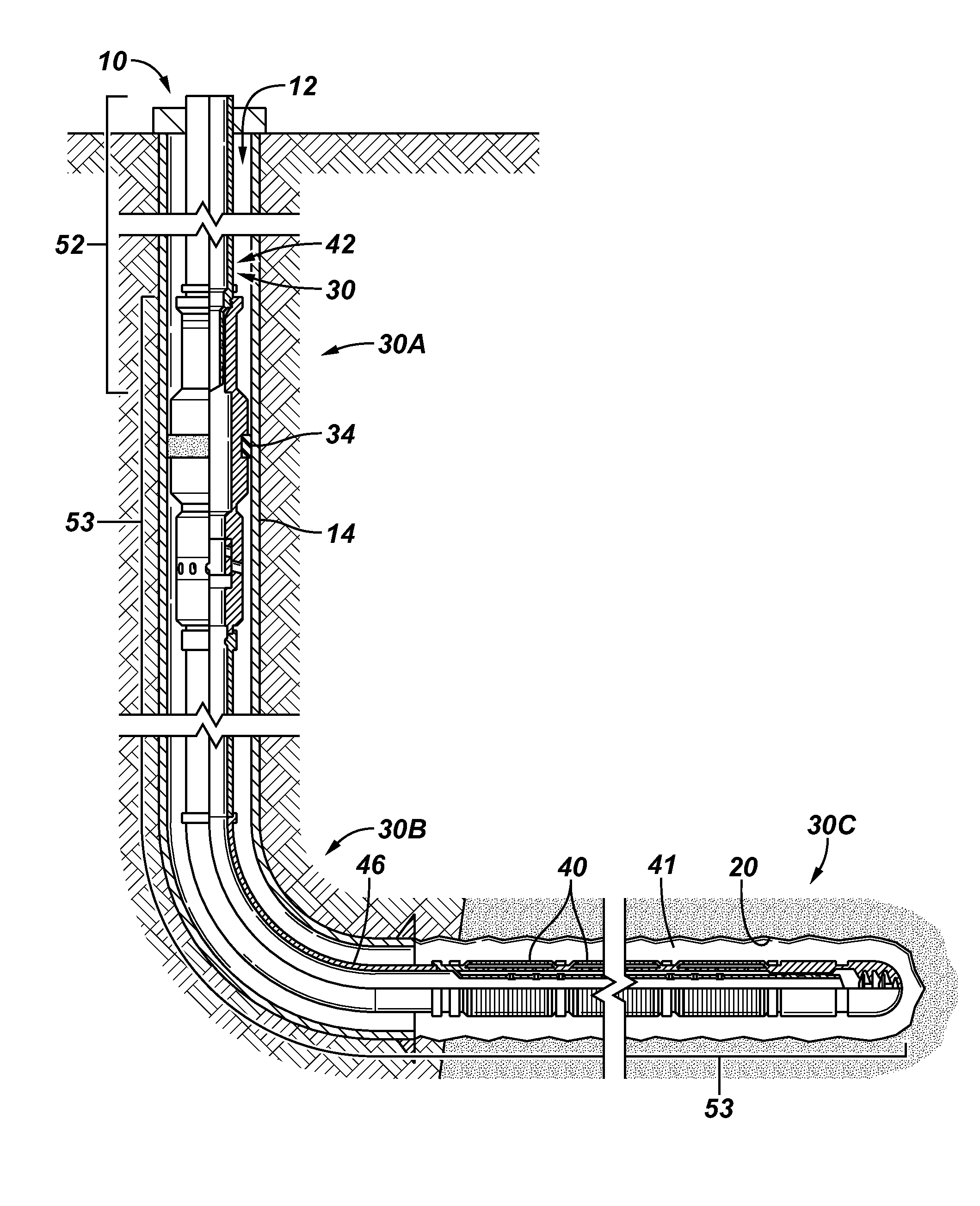
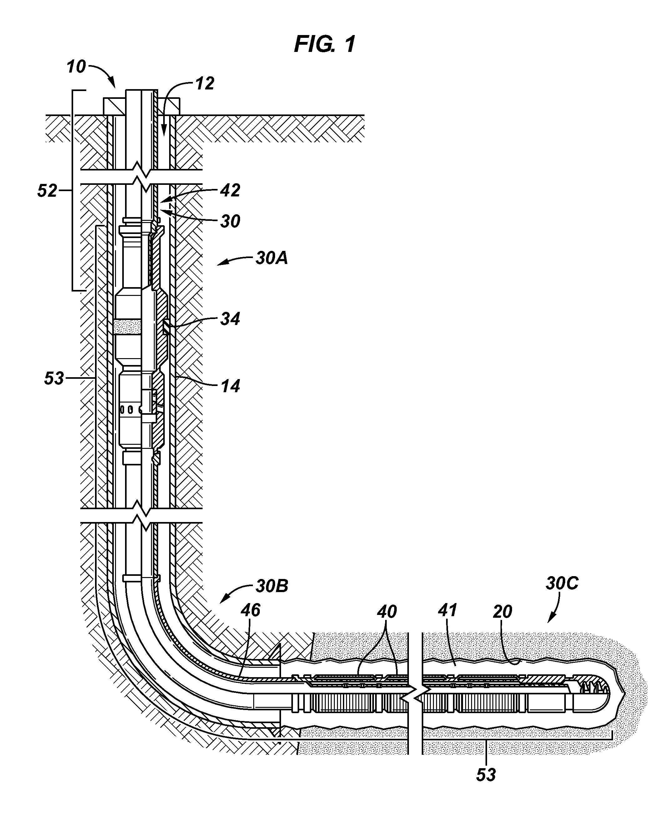
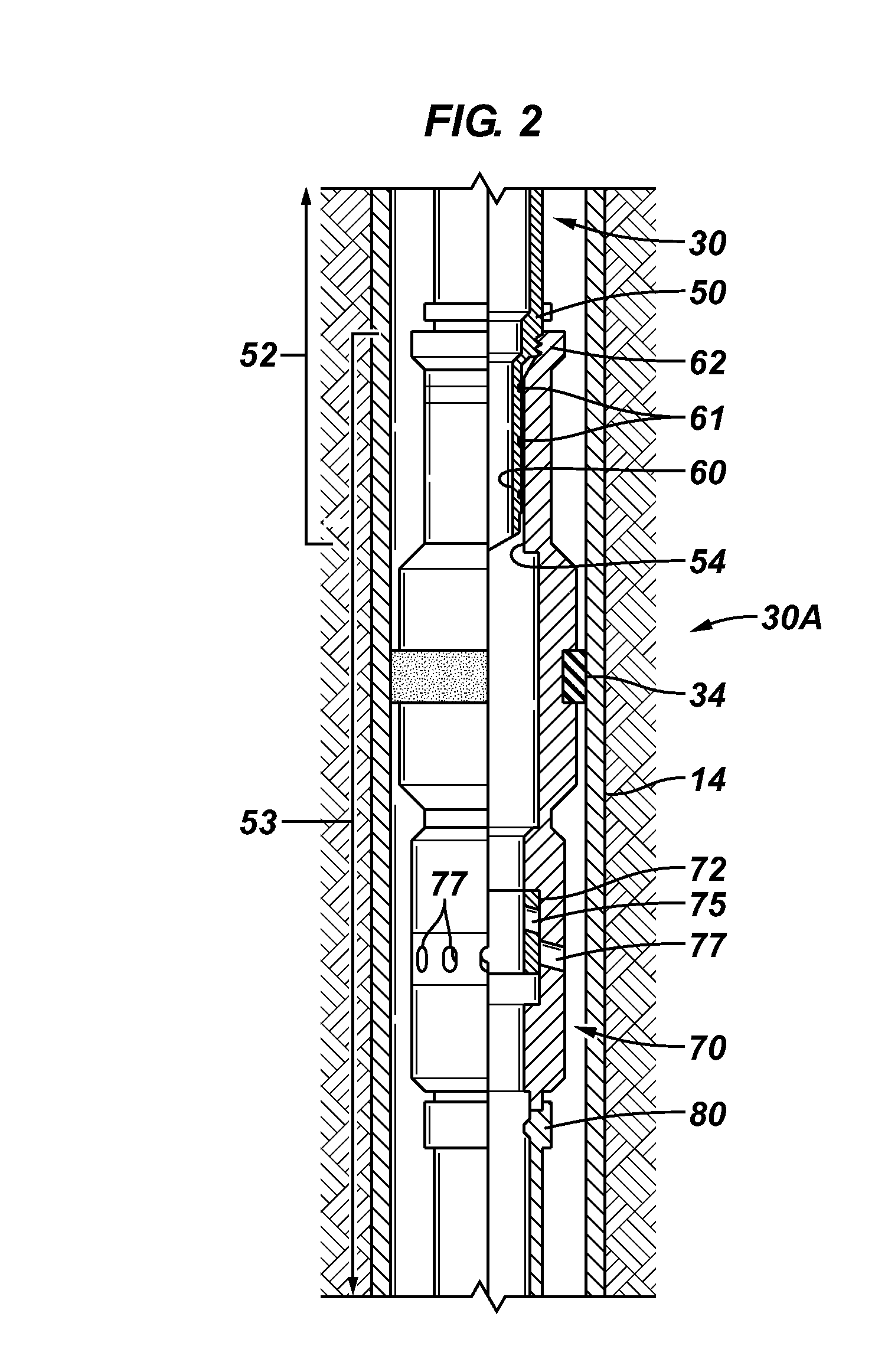
[0009]In an example, a completion system that is usable with a well may include a packer, a screen, at least one isolation valve and an annulus communication valve. The screen communicates well fluid between an annulus of the well and an interior passageway of the completion system. The isolation valve(s) may each be radially disposed inside the screen to control communication through the screen between the annulus and the interior passageway. The annulus communication valve may be located downhole of the packer and uphole of the screen to also control communication between the annulus and the interior passageway of the well. The packer, screen, isolation valve(s) and the annulus communication valve are adapted to be run downhole as a unit into the well.

Problems solved by technology

Each trip into the well adds to the cost and complexity of completing the well.

Method used


Image

  • Single trip well completion system
  • Single trip well completion system
  • Single trip well completion system

Examples


Embodiment Construction

[0019]In the following description, numerous details are set forth to provide an understanding of embodiments of the present invention. However, it will be understood by those skilled in the art that the present invention may be practiced without these details and that numerous variations or modifications from the described embodiments may be possible.

[0020]In the specification and appended claims: the terms “connect”, “connection”, “connected”, “in connection with”, and “connecting” are used to mean “in direct connection with” or “in connection with via another element”; and the term “set” is used to mean “one element” or “more than one element”. As used herein, the terms “up” and “down”, “upper” and “lower”, “upwardly” and downwardly“, “upstream” and “downstream”; “above” and “below”; and other like terms indicating relative positions above or below a given point or element are used in this description to more clearly describe some embodiments of the invention. Moreover, the term ...


PUM


Abstract

A completion system that is usable with a well may include a packer, a screen, an isolation valve and an annulus communication valve. The screen communicates well fluid between an annulus of the well and an interior passageway of the completion system. The isolation valve is radially disposed inside the screen to control communication through the screen between the annulus and the interior passageway. The annulus communication valve is located downhole of the packer and uphole of the screen to control communication with the annulus of the well. The packer, screen, isolation valve and the annulus communication valve are adapted to be run downhole as a unit into the well as a single trip completion.

Description

RELATED APPLICATIONS[0001]This application claims the benefit under 35 U.S.C. §119(e) to U.S. Provisional Patent Application Ser. No. 61 / 144,580, entitled, “SINGLE TRIP COMPLETION SYSTEM,” filed on Jan. 14, 2009, and U.S. Provisional Patent Application Ser. No. 61 / 157,627, entitled, “SINGLE TRIP COMPLETION SYSTEM,” filed on Mar. 5, 2009. Each of these applications is hereby incorporated by reference in its entirety.BACKGROUND[0002]1. Field of Invention[0003]The invention generally relates to a single trip well completion system.[0004]2. Description of the Related Art[0005]The following descriptions and examples are not admitted to be prior art by virtue of their inclusion in this section.[0006]For purposes of forming a well to extract a hydrocarbon-based fluid (oil or natural gas) from a subterranean, hydrocarbon-bearing geologic formation, or to inject water into or around a subterranean, geologic formation, for example, among other purposes not specifically identified but included...

Claims


Application Information

Patent Timeline
Patent Type & Authority Applications(United States)
IPC IPC(8): E21B23/00E21B34/10
CPCE21B43/08E21B34/10
Inventor DEBARD, JULIENESTILETTE, JR., FELIXPATEL, DINESH R.STAMM, BRYAN
Owner SCHLUMBERGER TECH CORP
Learn More