Brake disk

Active Publication Date: 2010-07-15
ROBERT BOSCH GMBH
View PDF7 Cites 8 Cited by
  • Summary
  • Abstract
  • Description
  • Claims
  • Application Information

AI Technical Summary

Benefits of technology

[0011]As an alternative, the air routing elements may be situated on a separate support element. This permits a great variety of variants of brake disks to be produced in a simple manner, for instance through different types of air routing elements, without requiring changes in the brake cup or the friction ring.
[0012]The flow direction of the cooling air is

Problems solved by technology

Furthermore, because the support section and one of the two friction rings are designed as one piece or as

Method used


Image

  • Brake disk
  • Brake disk
  • Brake disk

Examples


Example

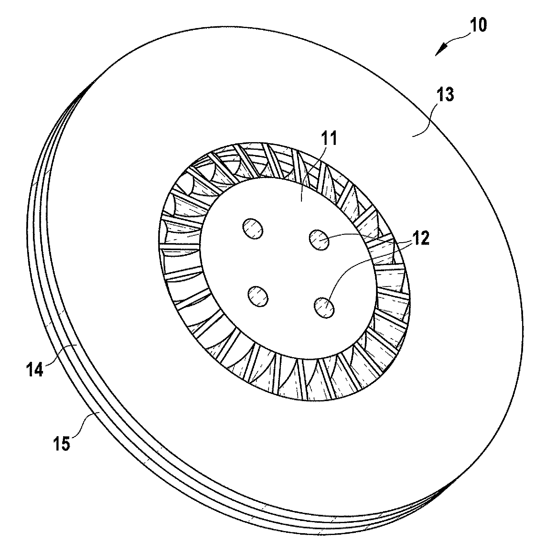
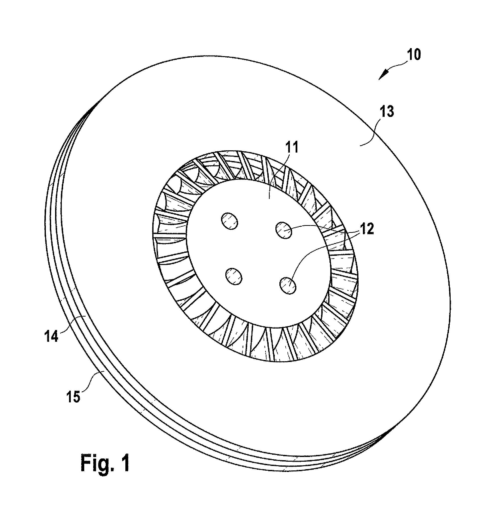
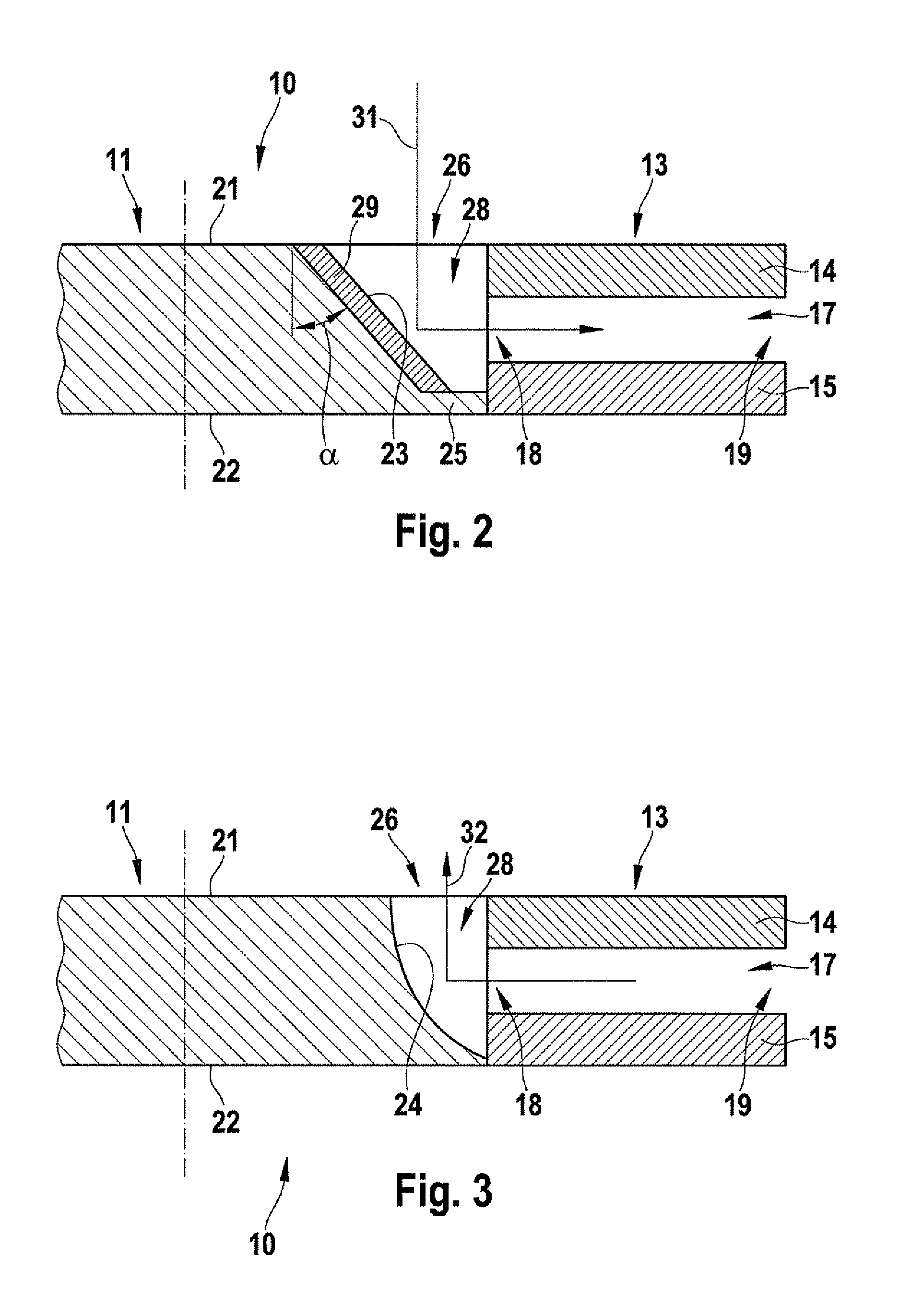
[0017]FIG. 1 shows an internally ventilated brake disk 10 for a motor vehicle. Brake disk 10 has a centrally situated brake cup 11, in which four holes 12, for example, are formed to fix brake disk 10 in place on a hub (not shown) of the motor vehicle. Brake cup 11 is surrounded by a friction ring 13, which is made up of two friction ring halves 14, 15. The two friction ring halves 14, 15, situated parallel to one another, are interconnected in the known manner with the aid of connecting webs (not shown), cooling channels 17 being formed between the two friction ring halves 14, 15 (FIGS. 2 and 3). Cooling channels 17 extend in the form of a star between region 18 lying radially inside, and region 19 of friction ring 13 lying radially outside. Friction ring halves 14, 15 cooperate with brake pads of the motor vehicle in the known manner, the heat generated in friction ring 13 due to friction heat being routed partially out of friction ring 13 via cooling channels 17.

[0018]As can be g...


PUM


Abstract

A brake disk is made up essentially of a brake cup and a friction ring. The friction ring includes two friction ring halves, between which cooling channels are situated. Additional air routing elements are situated at the level between the friction ring halves. The brake disk has especially satisfactory cooling characteristics.

Description

BACKGROUND INFORMATION[0001]A brake disk is described in German Patent No. 195 05 014. The brake disk is designed as an internally ventilated brake disk having cooling channels disposed between two friction rings. In order to improve the heat dissipation, the brake disk is provided with additional air routing elements. The air routing elements are situated on the side of the friction rings lying radially on the inside, in a plane outside the two friction rings on a support section. The support section and one of the two friction rings are designed as a single piece or as a common component. The brake disk has a relatively large design volume, especially a relatively large height or thickness. Furthermore, because the support section and one of the two friction rings are designed as one piece or as a common component, in particular from casting material, the weight of the brake disk is relatively high.[0002]In addition, it is described in European Patent No. EP 0 680 571, for example...

Claims


Application Information

Patent Timeline
IPC IPC(8): F16D65/12
CPCF16D65/128F16D2065/788F16D2065/1328F16D65/847
Inventor HOLZSCHUH, RALPHLEONHARDT, MATTHIAS
Owner ROBERT BOSCH GMBH
Why Eureka
Try Eureka