Display device with touch panel

a display device and touch panel technology, applied in the field of display devices with touch panels, can solve the problems of difficult to reduce the gap between transparent electrodes, the method cannot maintain the desired detection accuracy, and the voltage drop becomes small, so as to achieve excellent touch feeling to users, and excellent touch feeling

Active Publication Date: 2010-07-15
JAPAN DISPLAY INC +1
View PDF21 Cites 30 Cited by
  • Summary
  • Abstract
  • Description
  • Claims
  • Application Information

AI Technical Summary

Benefits of technology

[0024]In view of such drawbacks, applicants of the present application proposed a touch panel which adopts the new detection structure (Japanese Patent Application 2007-149884). However, according to such a related art, since a plurality of lines are formed on a touch panel and hence, when a user moves a pen on an operation surface in a sliding manner, the user feels the surface unevenness. To overcome this drawback, the inventors of the present invention have made extensive studies to improve such a touch panel and have made a touch panel display device which gives further excellent touch feeling to a user.
[0025]Accordingly, it is an object of the present invention to provide a display device with a touch panel which gives excellent touch feeling to a user.
[0026](1) According to one aspect of the present invention, there is provided a disp...

Problems solved by technology

However, the transparent electrode having a narrow line width exhibits a high resistance value and hence, this method cannot maintain desired detection accuracy.
Further, when a thickness of the transparent electrode is increased, it is necessary to take a taper formed by etching into consideration and hence, it is difficult to decr...

Method used


Image

  • Display device with touch panel
  • Display device with touch panel
  • Display device with touch panel

Examples


Embodiment Construction

[0054]Hereinafter, an embodiment of the present invention is explained in conjunction with drawings.

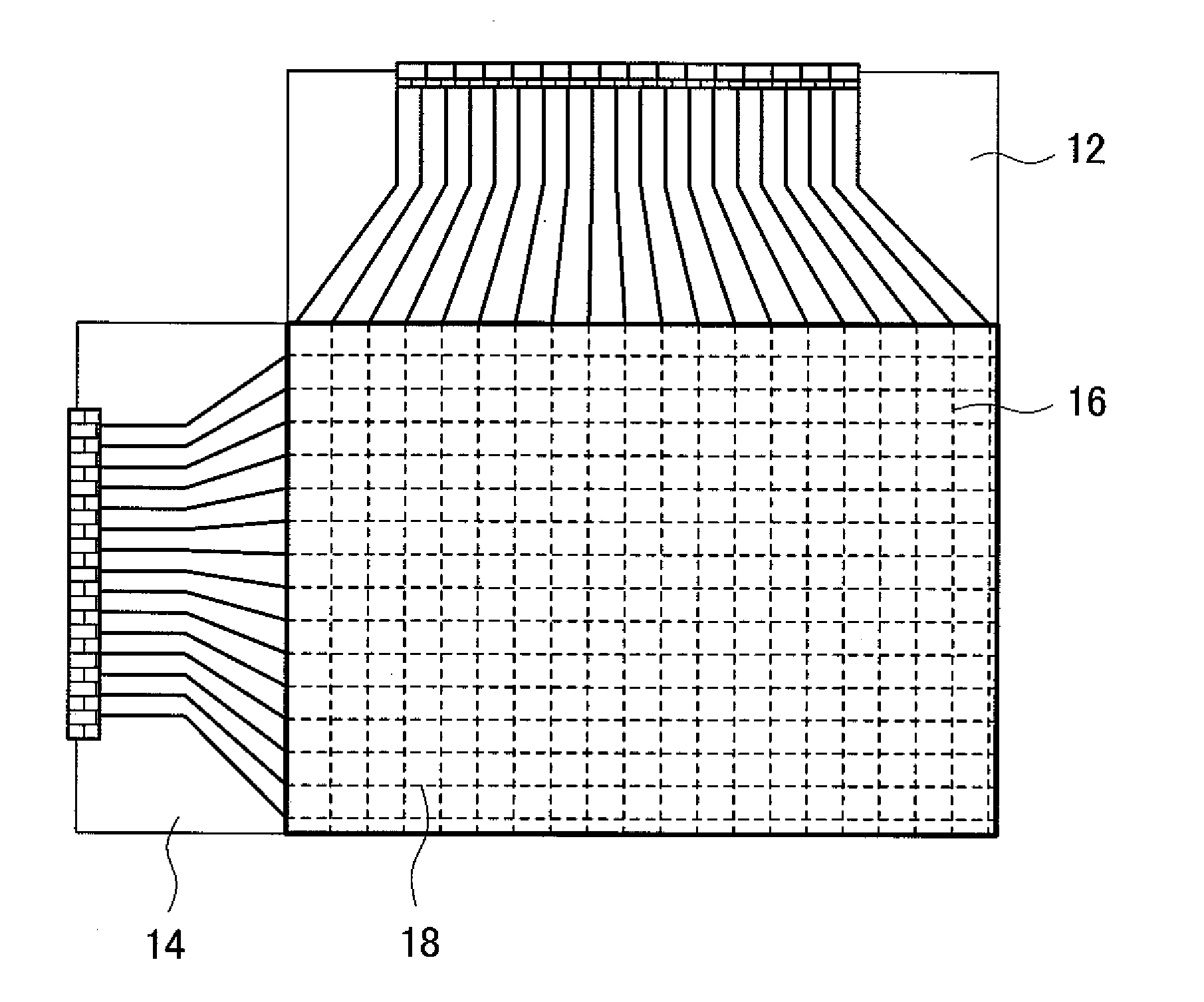
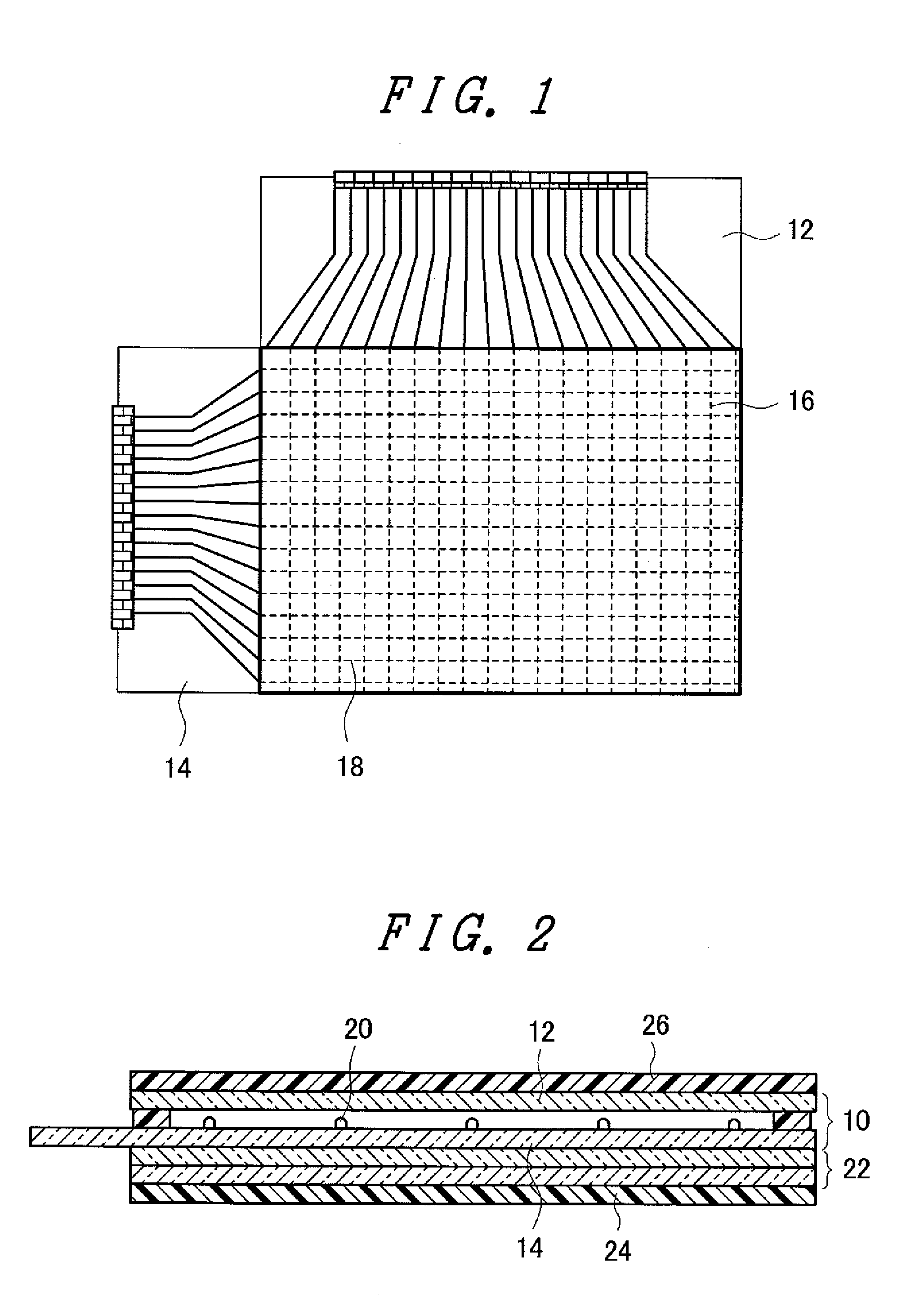
[0055]FIG. 1 is a plan view schematically showing a display device with a touch panel according to the embodiment of the present invention. FIG. 2 is a cross-sectional view schematically showing the display device with a touch panel according to the embodiment of the present invention.

[0056]The display device includes a touch panel (or referred to as “touch screen”) 10. The touch panel 10 includes a first substrate 12, and a second substrate 14 which is arranged to face the first substrate 12 in an opposed manner with a gap formed therebetween. On a surface of the first substrate 12 which faces the second substrate 14 in an opposed manner, a first electrode 16 which is constituted of a plurality of metal lines is formed (omitted from FIG. 2). On a surface of the second substrate 14 which faces the first substrate 12 in an opposed manner, a second electrode 18 is formed (omitted from F...


PUM


Abstract

The present invention provides a display device with a touch panel which gives a user excellent touch feeling. A display device with a touch panel includes: a touch panel which includes a first substrate, a second substrate arranged to face the first substrate in an opposed manner with a gap formed therebetween, a first electrode which is constituted of a plurality of metal lines formed on a surface of the first substrate which faces the second substrate, and a second electrode formed on a surface of the second substrate which faces the first substrate; a display panel which is mounted on the second substrate on a side opposite to the first substrate; and a resin film which is adhered to the first substrate on a side opposite to the second substrate.

Description

CROSS-REFERENCE TO RELATED APPLICATION[0001]The present application claims priority from Japanese application JP 2009-004874 filed on Jan. 13, 2009, the content of which is hereby incorporated by reference into this application.BACKGROUND OF THE INVENTION[0002]1. Field of the Invention[0003]The present invention relates to a display device with a touch panel.[0004]2. Background Art[0005]As one of detection methods mainly adopted by a conventional display device with a touch panel, there has been known a detection method which detects a change of light and a detection method which detects a change of an electric characteristic. With respect to these detection methods, the detection method which detects a change of light has a drawback that detection accuracy is not stable.[0006]On the other hand, as the detection method which detects a change of an electric characteristic, there has been known a resistance film method and a capacity method.[0007]FIG. 20 shows a conventional capacity-...

Claims


Application Information

Patent Timeline
IPC IPC(8): G06F3/041
CPCG06F3/047G06F3/045
Inventor OOKAWARA, TAKESHIMATSUDATE, NORIHARU
Owner JAPAN DISPLAY INC
Why Eureka
Try Eureka