Integrally molded surface fastener, and continuous production method and continuous production device therefor

a technology of integral molding and surface fasteners, which is applied in the direction of snap fasteners, buckles, filament/thread forming, etc., can solve the problems of high bending strength, high bending strength, and high bending strength, so as to improve bending strength, high plasticity, and the effect of increasing the stiffness of the engaging head

Active Publication Date: 2008-04-01
YKK CORP
View PDF16 Cites 32 Cited by
  • Summary
  • Abstract
  • Description
  • Claims
  • Application Information

AI Technical Summary

Benefits of technology

[0019]The present invention has been accomplished to solve these diversified problems and an object of the invention is to provide an integrally molded surface fastener which is capable of engaging minute dense fiber piles composed of unwoven fabric or knitted fabric in all directions securely, provides individual engaging elements with appropriate engaging force, shearing force and separation force, has an excellent tactile feeling on the surface of the surface fastener, secures a high engagement ratio with mating pile pieces, satisfies a durability demanded for this kind of fixing device and secures desired plasticity and tear strength of its flat base member, a production method therefor and a production device therefor.

Problems solved by technology

However, because in the engagement mechanism of the pile to the mushroom type engaging element, the pile engages in so-called hanging condition that it winds up around the neck portion, if it is intended to release the pile from the engaging head, the probability that the engaging element may be cut out or the pile itself may be cut out at the neck portion is high, so that this often cannot bear repeated usage and at a time, the engaging strength and separation strength likely increase excessively.
Thus, if it is intended to obtain engaging elements which engage / disengage minute piles like for example, unwoven cloth surface according to such a production method, naturally the thickness in the molding direction becomes very small, so that they are likely to buckle in the molding direction.
Thus, the stiffness cannot be improved until the thickness is increased.
In case of the molded surface fastener having the hook type engaging elements based on the aforementioned Japanese Patent Laid-Open Publication No. 9-322812 or Japanese Patent Laid-Open Publication No. 11-56413, although the fall-down of the erected portion decreases and the engagement ratio is secured because of the peculiar shape of the engaging element, necessary separation strength is more difficult to obtain as the minuteness progresses and increase in the separation strength to the disposable diaper and the like has been strongly demanded as described above.
As compared to the engaging element according to the Japanese Patent Application No. 2001-64460, although a high engagement ratio with a mating pile piece is secured by preventing the fall-down of the engaging element against a pressing force, so that the durability required for this kind of the fixing device is satisfied and desired plasticity and shearing strength of the flat base member can be secured, it cannot be said that its engaging force and separation strength are sufficient.
However, if it is intended to provide the root portion with a desired stiffness, the size of the root portion cannot help being increased.
If the diameter of the root portion increases, even if the extending length of the engaging head which extends from the root portion to all directions is to be minute, necessarily the diameter of the engaging head increases by the amount corresponding to the increase in the diameter of the root portion, so that no minute engaging element can be molded and if it is molded in a large size, naturally it is difficult to engage a loop.
Further, even if the engaging element is molded in a minute size, the so-called hanging, which occurs in the mushroom from the peculiar configuration, cannot be avoided and it is cut out easily between the pillar portion and the engaging head or the mating pile is cut out easily.
Thus, it is difficult to secure a necessary durability.
In case of a conventional integrally molded surface fastener, the engaging element can be molded in minute sizes, and for example, in case of the mushroom type engaging element, its separation strength is too high so that the minute pile or engaging element itself is likely to be damaged at the time of separation.
In case of the hook type engaging element, there is a problem that a desired separation strength cannot be secured although it never damage the minute piles or engaging elements itself.

Method used


Image

  • Integrally molded surface fastener, and continuous production method and continuous production device therefor
  • Integrally molded surface fastener, and continuous production method and continuous production device therefor
  • Integrally molded surface fastener, and continuous production method and continuous production device therefor

Examples


first embodiment

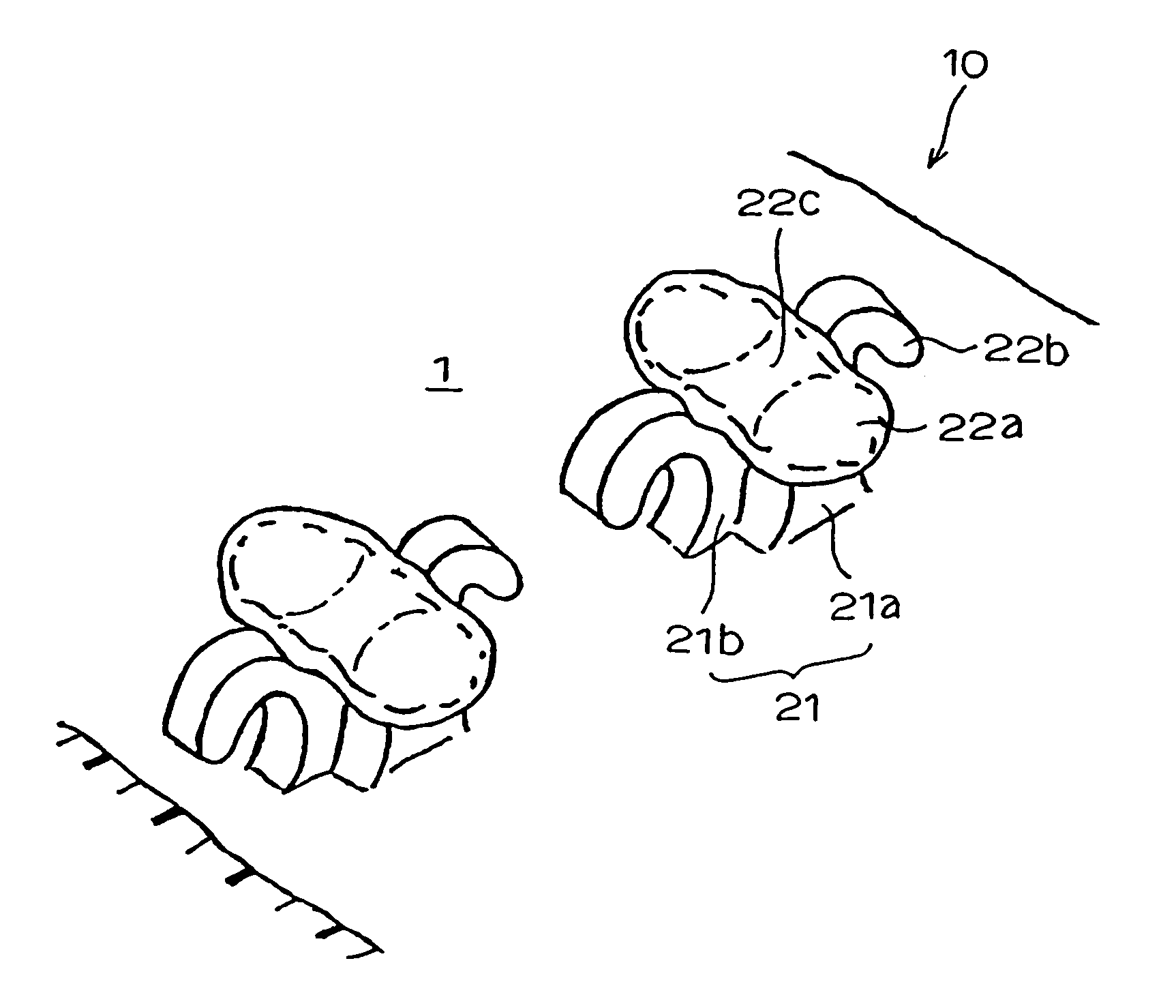
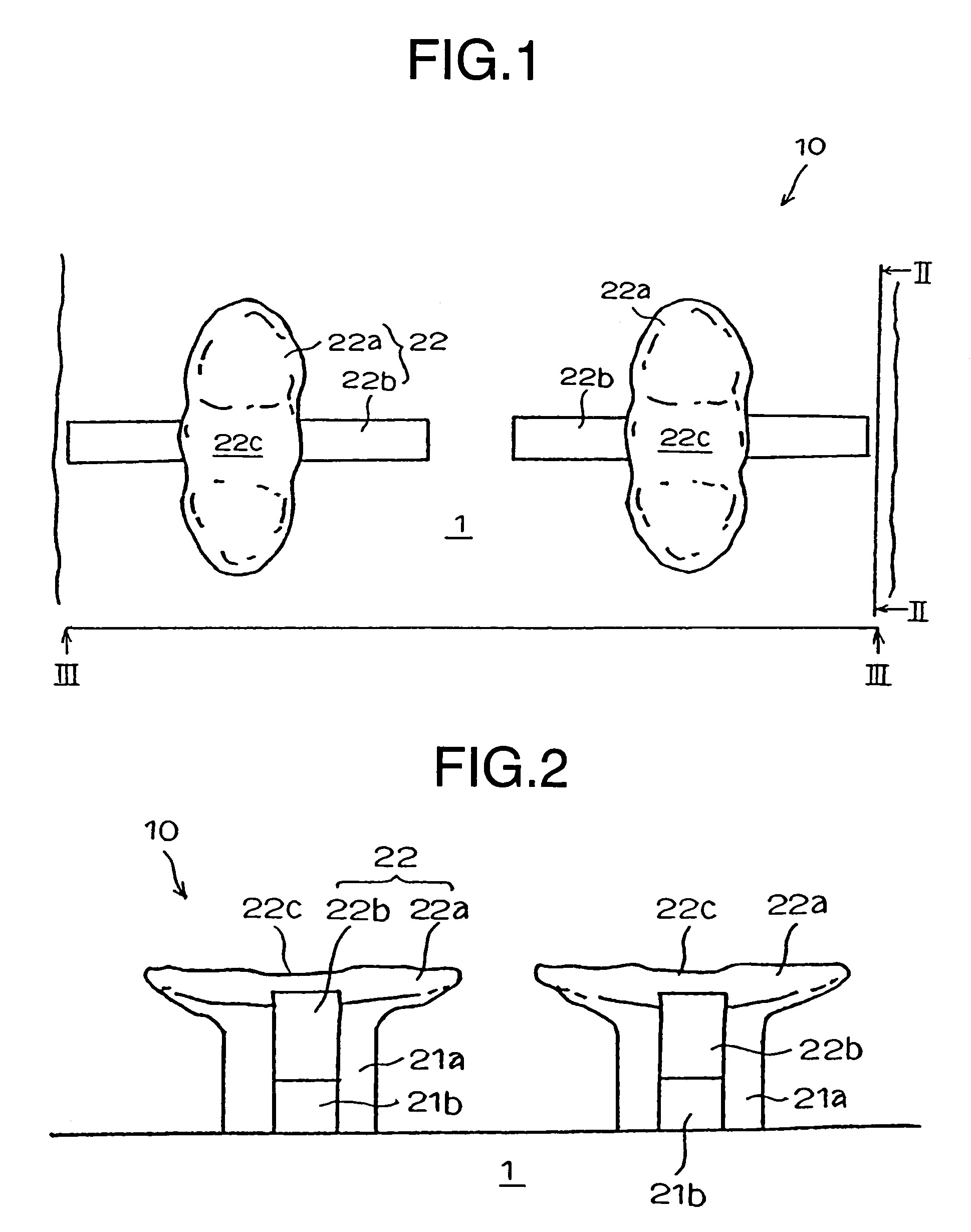
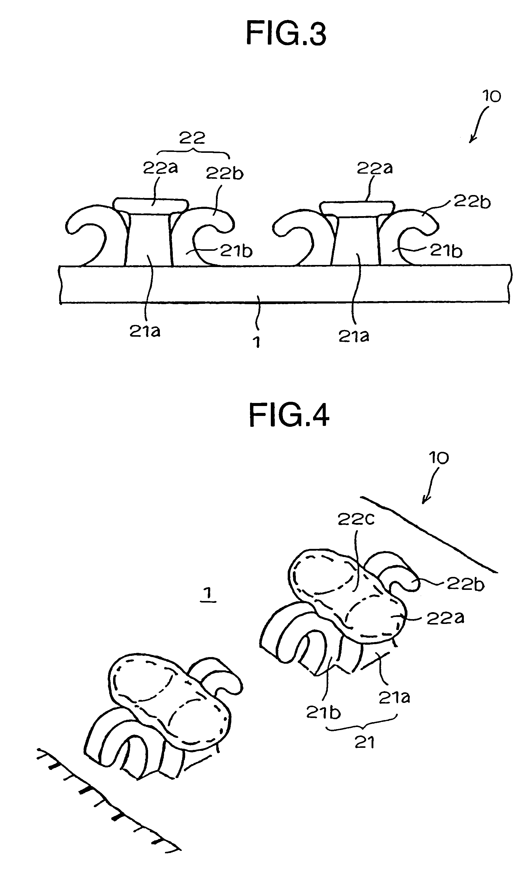
[0067]FIG. 1 is a partial plan view of a molded surface fastener having typical engaging element configuration according to the present invention. FIG. 2 is a sectional view taken along the line II-II, FIG. 3 is a sectional view taken along the line III-III and FIG. 4 is a perspective view of part of the molded surface fastener as seen from obliquely above.

[0068]An engaging element 2 of this embodiment comprises a pillar portion 21 rising vertically from a surface of a flat base member 1 and at its top end, an engaging head 22 including a first engaging portion 22a which extends in wing-like construction in opposite directions to each other, perpendicular to the molding direction (y direction) and a hook-like second engaging portion 22b which extends in opposite directions to each other with respect to the molding direction. The pillar portion 21 includes a first pillar portion 21a and a second pillar portion 21b, which are formed integrally such that they intersect each other at ri...

second embodiment

[0113]FIGS. 14 to 16 show the present invention. According to this embodiment (not shown), on the preliminary molding stage, the preliminarily molded first engaging portion erected linearly, which is a composition of the preliminarily molded element, is divided to ½ sections in the direction perpendicular to the molding direction (right and left) and for each section, hook-like preliminarily molded second engaging portions are extended in parallel to each other in opposite directions to each other along the molding direction from the first engaging portion.

[0114]By passing the preliminarily molded surface fastener having the preliminarily molded element 2′ having such a configuration through the with-heat pressing unit 150 shown in FIG. 8, which is a producing portion, the engaging element 2 having a configuration shown in FIGS. 14 to 16 is molded. For this engaging element 2, by pressing the preliminarily molded first engaging portion of the preliminarily molded element from above ...

third embodiment

[0115]FIGS. 17 and 18 show the present invention. As for the configuration of the engaging element 2 of this embodiment, as understood from the figures, a pair of the second engaging portions 22b extending in parallel back and forth in one direction are formed and the first engaging portion 22a composed of wing-like thin plate extends to the right and left across the right and left second engaging portions 22b in pair.

[0116]FIGS. 19A and 19B show a further modification of the second embodiment. According to this modification, the first engaging portion 22a composed of the wing-like thin plate and the second engaging portion 22b composed of hook piece are disposed such that they intersect at right angle as seen in a plan view and they provide a substantially letter L shape because they extend in each single direction with respect to the pillar portion 21 as seen in a top view. In case of this modification, because the first engaging portion 22a and the second engaging portion 22b do ...


PUM

PropertyMeasurementUnit
heightaaaaaaaaaa
heightaaaaaaaaaa
lengthaaaaaaaaaa

Abstract

In a molded surface fastener (10) having engaging elements (2) of minute dimension of thermoplastic resin molded together with a base member (1) by continuous molding, each engaging element (2) comprises first and second engaging portions (22a, 22b) each having a different configuration extending in parallel to a surface of the base member from a top end of a pillar portion (21) rising from the base member (1) such that they intersect at right angle. The second engaging head (22b) has an ordinary hook shape structure while the first engaging head (22a) has a wing-like thin plate structure as seen in a plan view.The engaging elements having such a structure in which each engaging element has appropriate engagement force, shearing force and separation force so as to keep an excellent tactile feeling of a surface of the surface fastener, prevents itself from falling down against a pressing force, secures a high engagement ratio with mating pile pieces and satisfies a durability.

Description

TECHNICAL FIELD[0001]The present invention relates to a surface fastener obtained by molding a flat base member and a number of engaging elements integrally and continuously using thermoplastic resin, a production method and production device therefor, and more particularly to an integrally molded surface fastener in which the engaging elements are unlikely to fall down despite their fine dimension and engage minute pile pieces of unwoven fabric securely so as to secure a specified engaging force, a separation force and a high engagement ratio, this integrally molded surface fastener being capable of enduring several engaging / disengaging operations sufficiently, and preferably applied to paper diaper, medical simple clothing, napkins, various kinds of working simple clothing, underwear and the like, and a production method and production device therefor.BACKGROUND ART[0002]In recent years, as a fastening device for disposable paper diaper, medical simple clothing, napkins, various k...

Claims


Application Information

Patent Timeline
Patent Type & Authority Patents(United States)
IPC IPC(8): A44B18/00
CPCA44B18/0061B29C43/222B29C43/46Y10T24/2792B29C2043/461
Inventor MINATO, TSUYOSHIGONDA, EIJIAKENO, MITSURU
Owner YKK CORP
Why Eureka
Try Eureka