Method, system and apparatus for controlling sensing devices of a HVAC system

a sensing device and hvac technology, applied in the field of energy consumption, can solve the problems of system failure to account for the thermal characteristics of the building, system failure to meet the needs of current weather conditions and temperature of the home, and laborious maintenance work, so as to reduce the impact of user comfort, maximise energy consumption, and improve the participation rate of incentive-based demand response programs

Inactive Publication Date: 2021-11-11
ZEN ECOSYST IP PTY LTD
View PDF5 Cites 0 Cited by
  • Summary
  • Abstract
  • Description
  • Claims
  • Application Information

AI Technical Summary

Benefits of technology

[0052]In another aspect of embodiments described herein there is provided a system for controlling a plurality of sensing devices, said system comprising an API service utilising a computer usable medium having computer readable program code and computer readable system code embodied on said medium for reducing peak energy usage across a group of the sensing devices within a data processing system, said computer program product including computer readable code within said computer usable medium for:
[0059]In yet a further aspect of embodiments described herein there is provided an apparatus adapted to control a plurality of sensing devices wherein each sensing device is operatively associated with a HVAC device within a HVAC system, said apparatus for reducing peak energy usage across a group of the sensing devices, said apparatus comprising:
[0068]flexibility for a user to control a trade-off between comfort or need and financial savings,
[0071]permits a market operator to precisely dictate a resource or load savings curve,
[0074]Furthermore, the solutions provided by embodiments of the present invention are expected to improve the participation rate of incentive-based demand response programs. Generally speaking, in an incentive-based demand response program an energy focused company will give participants incentives in the form of hardware rebates, bill discounts, among other things. The participant rate may be greatly affected as the inconvenience far outweighs the perceived savings to the participant. Embodiments of the invention reduce the impact to the user's comfort by ensuring that for a site with multiple AC units that these units will not be switched off or applied with a setback at the same time.
[0075]In addition, embodiments of the present invention can maximise the energy reduction for a given organisation that may have one or many AC units on a site as well as a group of sites. The method, system and apparatus of embodiments of the present invention when applied will systematically reduce energy usage of AC units while making sure that overall comfort is not greatly affected.

Problems solved by technology

This leads to a problem that batteries are replaced at different times for each wireless measurement terminal, whereby the maintenance work is laborious.
However, these systems require a user to configure them properly and adjust the times and temperatures to adapt to changing energy consumption or production needs.
However, adjustments are often based on incomplete or inaccurate weather information for the precise location of the home and do not factor in the occupants personal preferences.
In addition, these systems are generally not capable of accounting for the thermal characteristics of the building in which the thermostat is installed.
As a result, such systems are reactive to current weather conditions and temperature needs of the home, rather than performing pre-heating and / or pre-cooling based on forecast weather conditions and the energy characteristics of the home.
However, due to limitations of conventional energy management devices, such as thermostats and the like, it can be difficult for a residence to efficiently and effectively manage energy usage on its own.
Furthermore, conventional thermostat systems aim to maintain a desired temperature within a residence, but because they are not sufficiently precise the temperature fluctuates.
This fluctuation can result in varying energy consumption, and variable energy cost.
During peak energy demand periods, commercial energy providers (such as utilities providers and service providers) are often forced into short-term purchase of energy resources at premium prices and pass on the high costs to its energy customers.
Within commercial energy systems, when providers fail to maintain adequate energy resources, this can lead to power outages that affect the general public and can tarnish the reputation of the providers and adversely affect their business.
As a result, in these circumstances, providers often lose millions of dollars every day in order to maintain adequate energy resources.
However, due to the high volatility of wholesale energy prices and the absence of energy management systems for determining real-time information tracking energy usage, consumer participation in reduction compensation programs is limited.
This is considered cumbersome and inefficient.
This method relies on test steps to characterise the HVAC system, and therefore would require a certain amount of initial setup time when the system is offline, which is also considered cumbersome and inefficient.
This method requires the HVAC system to be in operation during a ramping period and therefore would require a certain amount of initial setup time where the system is offline, which is also considered cumbersome and inefficient.
It is considered this limits the system to a cumbersome and inefficient process.
There are some devices of the prior art which provide a greater level of detail about the energy usage in a building, but they all suffer from problems, such as the following:many existing devices do not offer a low-cost way for a person to be on-site to monitor or record a relevant parameter such as current drawn from an apparatus or appliance or air temperature or humidity, i.e. for remote monitoring or control of a parameter that may not be easy or convenient to be physically near to;the cost and complexity of installing and managing devices of the prior art often outweighs the benefits.
There are many partial solutions to one or more of the problems noted herein, but no known complete solutions to the entire problem.
By way of explanation known solutions of the prior art as identified herein have at least a major disadvantage in that they control apparatus function load, such as air conditioning load, only.
This is generally unacceptable to consumers of energy.
Aside from the issue of not wanting an outside party such as a public utility or an authority that could be seen as “big brother” imposing to turn a consumer's AC off, if a house gets very hot then this circumstance may become a potentially life-threatening health issue for occupants.
In the latter circumstance prior art devices, by definition, do not take into account the internal temperature of a dwelling which they are controlling and so can be considered a life-threatening health hazard in the extreme but not uncommon circumstance.

Method used


Image

  • Method, system and apparatus for controlling sensing devices of a HVAC system
  • Method, system and apparatus for controlling sensing devices of a HVAC system
  • Method, system and apparatus for controlling sensing devices of a HVAC system

Examples


example 1

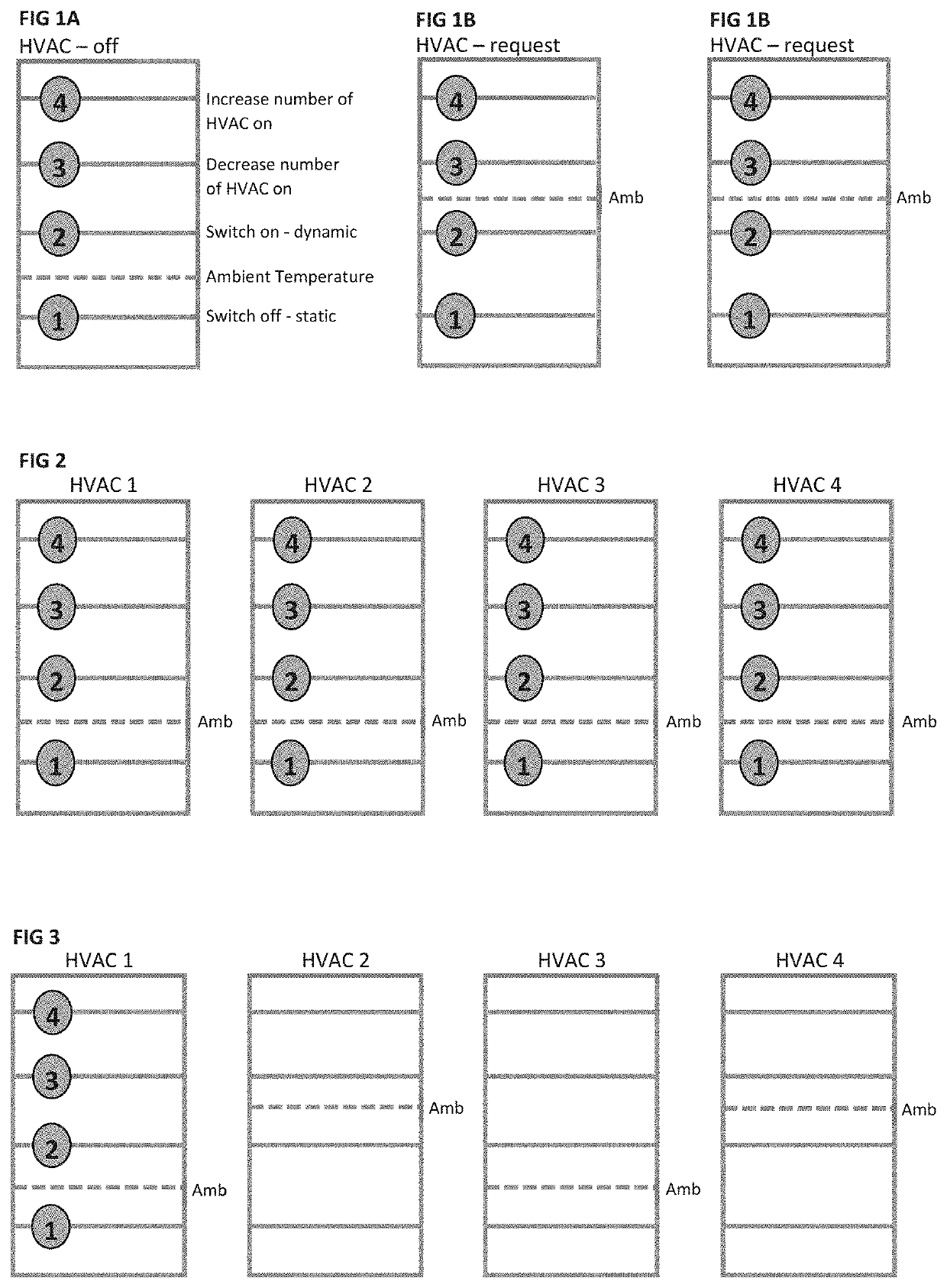
[0098]FIG. 2 illustrates Example 1, in which all HVACs are off and ambient temperature is below SP1.

example 2

[0099]FIG. 3 illustrates Example 2, in which a predetermined number of HVACs are running. Specifically, two HVACs (HVAC 2 and HVAC 4) are on.

example 3

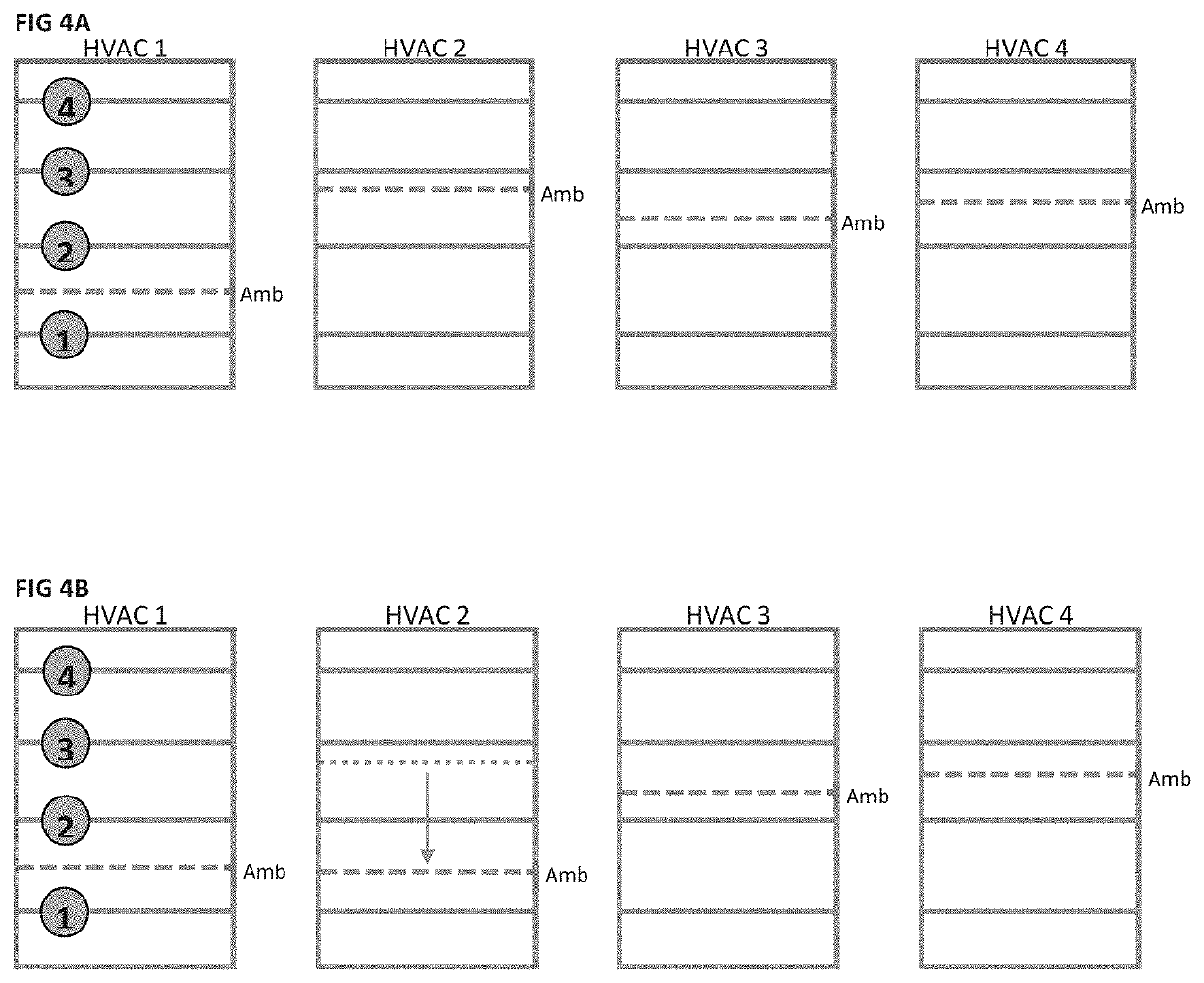
[0100]FIG. 4A illustrates Example 3, in which a predetermined number of HVACs are ON. One or more additional HVACs are requesting to be ON. Specifically, HVAC 3 has requested permission to switchON. However, before this can occur, one other HVAC must switch off, e.g. HVAC 2 or HVAC 4.

[0101]FIG. 4B illustrates the next phase of Example 3 when, during a grace period, (e.g. 10 minutes) a HVAC (e.g. HVAC 2) can be turned OFF as the ambient temperature decreases below SP2 (arrow). HVAC 2 would not turn OFF in the absence of a request because it has not reached yet SP1.

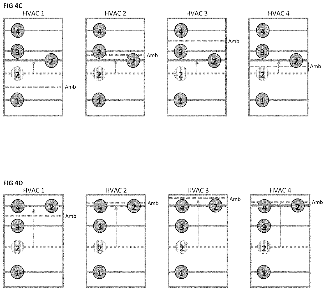
[0102]FIG. 4C illustrates a further phase of Example 3 when the ambient temperature of the rooms with HVAC ON does not fall below SP2 during the grace period, leading to an increase in SP2 to compensate. As a result, HVAC 4 can be switched off as the ambient temperature is below SP2.

[0103]FIG. 4D illustrates the next phase of Example 4 when increasing SP2 (FIG. 4C) with the aim of at switching OFF a HVAC that is currently r...


PUM


Abstract

The present application relates to the field of energy consumption. In one form, a method of controlling a number of sensing devices includes the steps of: forming a queue of a number of sensing devices, selecting one of the sensing devices, storing the settings of the selected sensing device, determining at least one active mode of the selected sensing device, calculating a sleep time for the selected sensing device, and operating the selected device with its stored settings in accordance with the calculated sleep time.

Description

FIELD OF INVENTION[0001]The present invention relates to the field of energy consumption. In particular, the invention relates to a method, system and apparatus for controlling and optimising energy consumption of a building and / or energy consuming appliances, equipment or devices of a building. It will be convenient to hereinafter describe the invention in relation to the use of an API service in providing control over a plurality of thermostats to reduce peak energy usage across a group of thermostats, however it should be appreciated that the present invention is not limited to that use, only. For example, it will be readily apparent to the person skilled in the art that the present invention could be extended to control of other devices such as water pumps to reduce peak water usage across a group of pumps.BACKGROUND ART[0002]Throughout this specification the use of the word “inventor” in singular form may be taken as reference to one (singular) inventor or more than one (plural...

Claims


Application Information

Patent Timeline
Patent Type & Authority Applications(United States)
IPC IPC(8): F24F11/47F24F11/49F24F11/56
CPCF24F11/47F24F11/56F24F11/49G05D23/1934G05D23/1951G05D23/1904F24F2120/14H02J3/008G05D23/1932G05D23/1917G05B2219/2642H02J3/003H02J2310/14H02J2310/64H02J2310/60H02J3/14H02J3/00G05D23/19Y04S50/10
Inventor MCPHAIL, JAMES LAWRENCEMURACA, JAMESHATAMOSA, GRANT IAN L.
Owner ZEN ECOSYST IP PTY LTD
Why Eureka
Try Eureka