
Active rise and fall time compensation algorithm

a compensation algorithm and active technology, applied in the field of radiation diagnosis, can solve the problems of increasing the rise time of the pulse, falling instantaneously, and applying kilovoltage decay with some delay

Pending Publication Date: 2022-05-26
KONINKLJIJKE PHILIPS NV
View PDF3 Cites 0 Cited by
  • Summary
  • Abstract
  • Description
  • Claims
  • Application Information

AI Technical Summary

Benefits of technology

The present invention is an X-ray system with improved pulse width correction to compensate for temperature-related changes in electronics. This allows for better dosage of X-ray and more accurate average current through the X-ray tube, resulting in better image quality and easier compliance with international standards. Additionally, the invention allows for a modular device that can be used for mobile surgery applications, with a wide range of usable pulse widths and highly accurate pulses even at low pulse energy levels, resulting in a more compact power supply and reduced peak energy usage.

Problems solved by technology

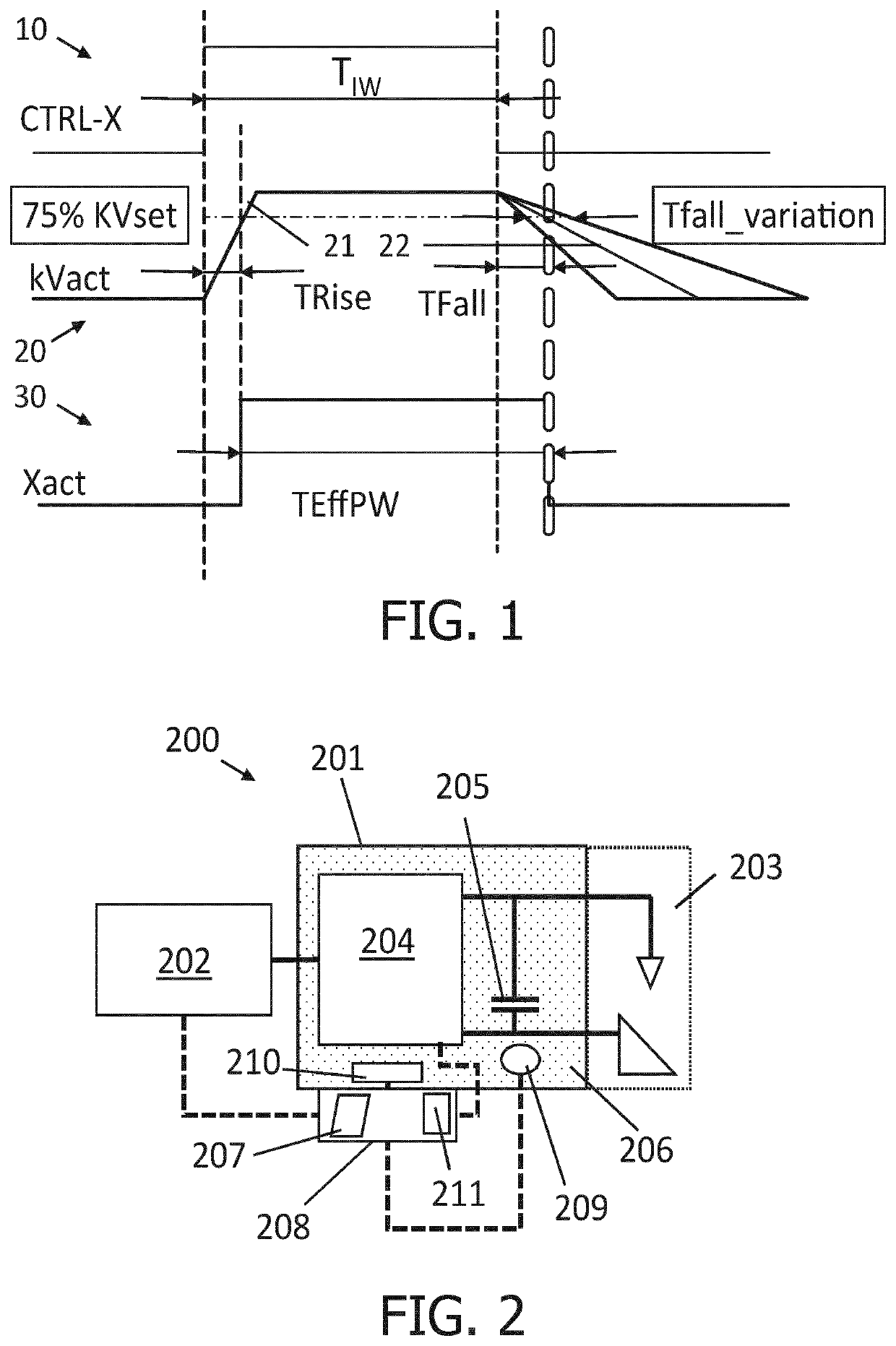
Due to wiring and circuitry, when a voltage setting (e.g. a square wave) pulse is applied to energize an X-ray tube anode, the cable and circuitry capacity results in an increased rise time of the pulse.
On the other hand, when the voltage is removed at the end of the pulse to terminate the x-ray exposure, discharge of the cable and circuitry capacitive current results in the applied kilovoltage decaying with some delay, instead of falling instantaneously.
However, for short duration x-ray exposures, such as below 20 ms, the rise and decay times represent a substantial percentage of the exposure interval.
Moreover, these inaccuracies are more difficult to predict, and settings of the X-ray system outside of a range of optimal setting values may require compensation in order to achieve improved accuracies.

Method used


Image

  • Active rise and fall time compensation algorithm
  • Active rise and fall time compensation algorithm
  • Active rise and fall time compensation algorithm

Examples


Embodiment Construction

[0049]The present invention will be described with respect to particular embodiments and with reference to certain drawings but the invention is not limited thereto but only by the claims. The dimensions and the relative dimensions do not correspond to actual reductions to practice of the invention.

[0050]Furthermore, the terms first, second and the like in the description and in the claims, are used for distinguishing between similar elements and not necessarily for describing a sequence, either temporally, spatially, in ranking or in any other manner. It is to be understood that the terms so used are interchangeable under appropriate circumstances and that the embodiments of the invention described herein are capable of operation in other sequences than described or illustrated herein.

[0051]Moreover, the terms top, under and the like in the description and the claims are used for descriptive purposes and not necessarily for describing relative positions. It is to be understood that...


PUM


Abstract

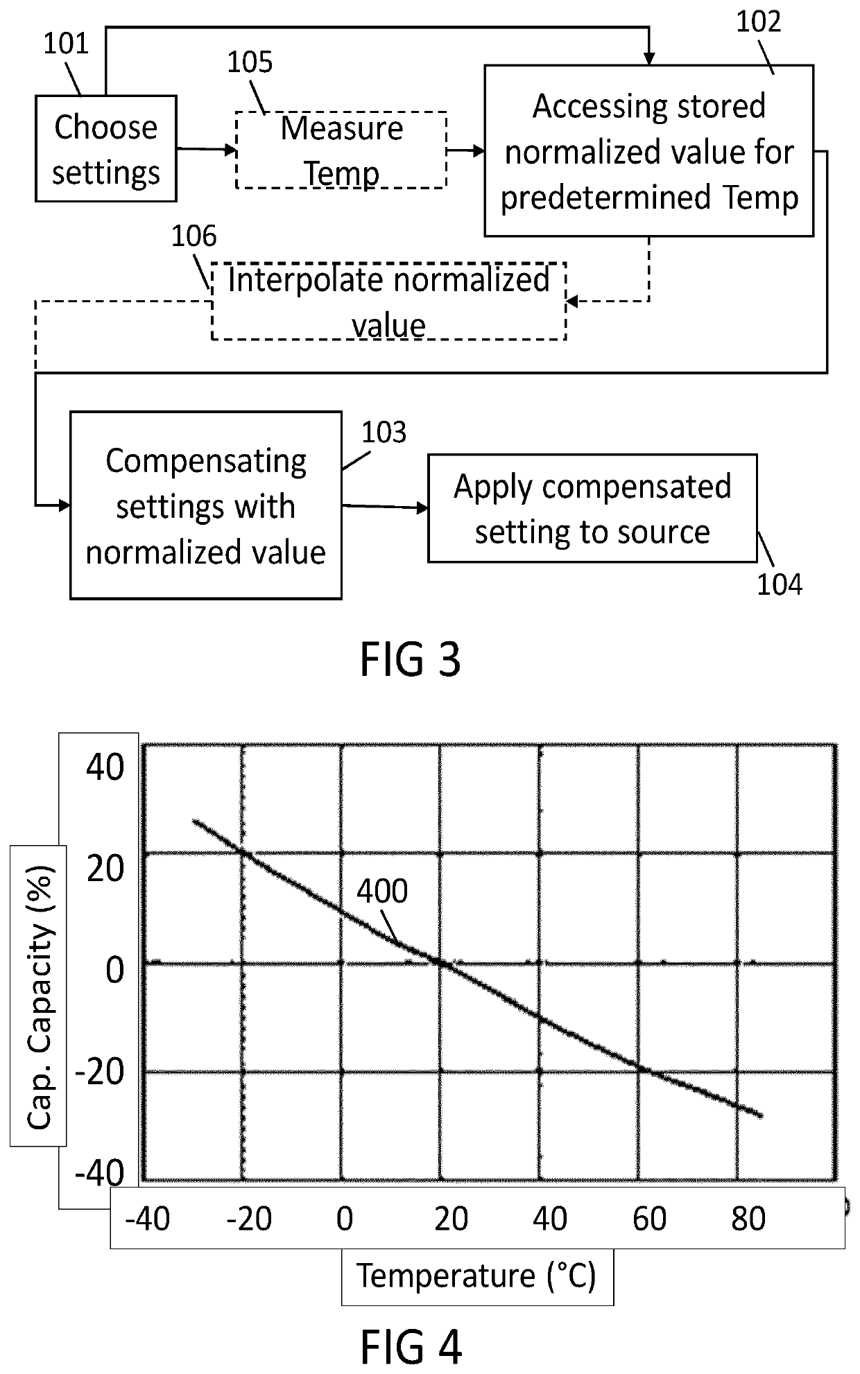
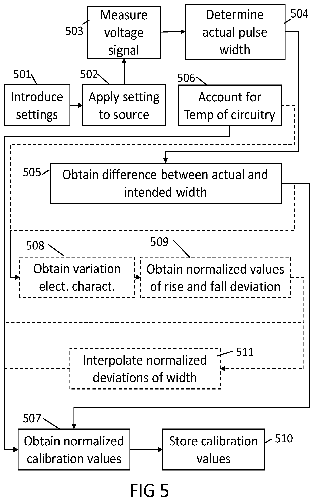
A method is provided for compensating the settings of a pulsed X-ray system. A current, voltage and intended pulse width settings are selected for the X-ray pulses to be provided. Then, the selected pulse width setting for the set voltage and tube current is compensated, in accordance with stored normalized value or values at a predetermined temperature, taking into account the environmental temperature of the electric circuitry of the X-ray tank. The normalized values are obtained in a calibration step from the actual or effective pulse width and the difference thereof with the intended width, normalizing said value with the temperature of the circuitry providing pulsed voltage and current to the source.

Description

FIELD OF THE INVENTION[0001]The invention relates to the field of radiation diagnosis. More specifically it relates to method of generating X-ray pulses, activating and calibrating an X-ray system, software products and systems and to related calibrated X-ray systems.BACKGROUND OF THE INVENTION[0002]In an X-ray machine, several different X-ray patterns can be generated. Depending on the application, the surgeon, the type of surgery, and / or the components used in the X-ray machine, some X-ray patterns have benefits over others. One of the possible X-ray patterns is a pulsed pattern, in which X-rays are generated with a predetermined duty cycle.[0003]As per international regulations, the applied X-ray parameters shall be reported to the user, within defined accuracies. Specifically, for many applications (including medical and surgery applications) the intended average tube current shall be accurate within 20% of the current actually applied to the tube, for any setting selectable by ...

Claims


Application Information

Patent Timeline
IPC IPC(8): H05G1/32H05G1/04H05G1/22H05G1/36H05G1/26
CPCH05G1/32H05G1/04H05G1/265H05G1/36H05G1/22
Inventor VAN BRUSSEL, JEROEN
Owner KONINKLJIJKE PHILIPS NV
Learn More