Power transmission device

a transmission device and transmission technology, applied in the direction of gearing, hoisting equipment, gearing elements, etc., can solve the problems of reducing the contact area between the teeth of the worm and the worm gear, reducing the engagement rate therebetween, and attempting to use, so as to improve the engagement rate of the gear, enhance the power transmission efficiency, and reduce the wear of the gear

Active Publication Date: 2022-11-01
PARALLOID GEAR CO LTD
View PDF15 Cites 0 Cited by
  • Summary
  • Abstract
  • Description
  • Claims
  • Application Information

AI Technical Summary

Benefits of technology

[0023]According to the present invention, it is possible to improve the engagement rate of gears while reducing wear of the gears, and enhance the power transmission efficiency.

Problems solved by technology

Therefore, there is a problem that a mutual contact area between the teeth of the worm and the worm gear is decreased, and as a result, an engagement rate therebetween is reduced.
However, the conventional power transmission device uses such the Janggu-shaped worm and worm gear in a limited manner, and there has been no attempt to use it with various types of gears by taking full advantage of the characteristics of the Janggu-shaped worm.

Method used


Image

  • Power transmission device
  • Power transmission device
  • Power transmission device

Examples


first embodiment

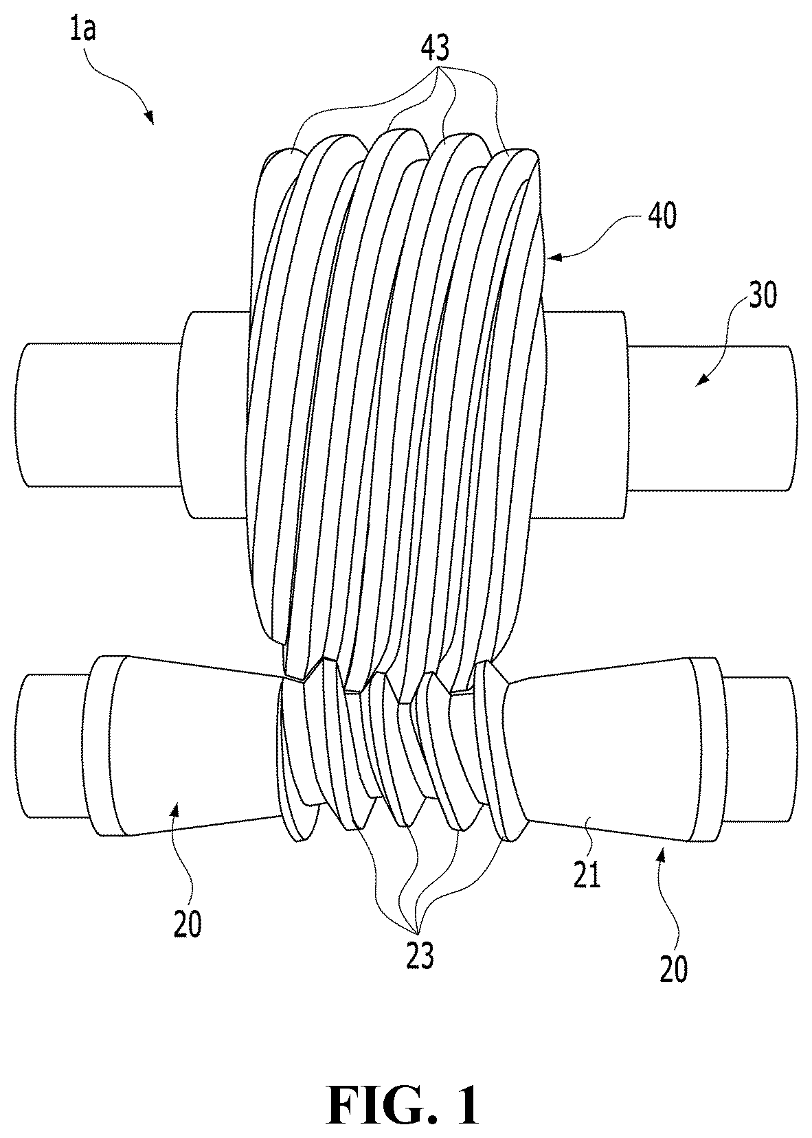
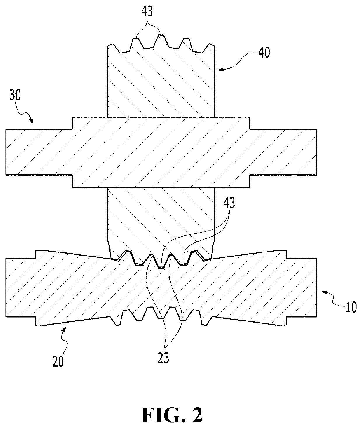
[0035]FIGS. 1 and 2 show a power transmission device according to the present invention.

[0036]As shown in FIGS. 1 and 2, a power transmission device 1a according to the first embodiment of the present invention includes a worm shaft 10, a Janggu-shaped worm 20, a first transmission shaft 30, and a first transmission gear 40.

[0037]The worm shaft 10 has a rod shape of a circular cross section having a predetermined length. Both ends of the worm shaft 10 are rotatably supported by bearings (not illustrated).

[0038]The Janggu-shaped worm 20 is provided in a central region of the worm shaft 10. The Janggu-shaped worm 20 forms a diameter-reduced part 21 whose outer diameter is increased toward both ends from a center thereof in an axial direction of the worm shaft 10.

[0039]Worm teeth 23 are formed on the diameter-reduced part 21. The worm teeth 23 have various axial modules, various lead angles, and various axial pitches according to the various pitch diameters, and are continuously formed...

second embodiment

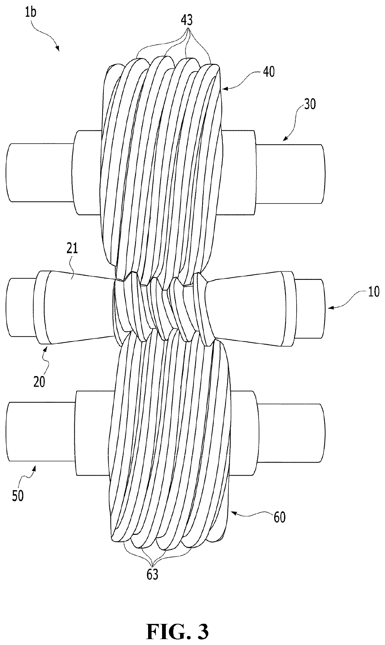
[0054]Meanwhile, FIGS. 3 and 4 show a power transmission device according to the present invention.

[0055]Unlike the first embodiment, a power transmission device 1b according to the second embodiment of the present invention has a configuration in which a second transmission shaft 50 and a second transmission gear 60 having the same structure as the first transmission shaft 30 and the first transmission gear 40 are disposed opposite to each other with the worm shaft 10 and the Janggu-shaped worm 20 interposed therebetween.

[0056]That is, the second transmission shaft 50 is disposed to face the first transmission shaft 30 in parallel thereto with the worm shaft 10 interposed therebetween.

[0057]The second transmission shaft 50 is disposed in parallel to the worm shaft 10 at an interval. Both ends of the second transmission shaft 50 are rotatably supported by bearings (not illustrated). In addition, the second transmission shaft 50 may be supported by the bearings so as not to move from...

third embodiment

[0070]FIGS. 5 and 6 show a power transmission device according to the present invention.

[0071]Unlike the above-described first embodiment, a power transmission device 1c according to the third embodiment of the present invention further includes a third transmission shaft 70 and a third transmission gear 80.

[0072]The third transmission shaft 70 is disposed to face the first transmission shaft 30 orthogonal thereto with the worm shaft 10 interposed therebetween.

[0073]The third transmission shaft 70 is disposed orthogonal to the worm shaft 10 at an interval. Both ends of the third transmission shaft 70 are rotatably supported by bearings (not illustrated). In addition, the third transmission shaft 70 may be supported by bearings so as not to move from side to side in an axial direction of the third transmission shaft 70.

[0074]The third transmission gear 80 has a disk shape with a predetermined thickness. The outer periphery of the third transmission gear 80 is formed in a substantiall...


PUM


Abstract

The present invention relates to a power transmission device, which includes: a worm shaft; a Janggu (slim waist drum)-shaped worm which is provided on the worm shaft, and has a diameter-reduced part whose outer diameter is increased toward both ends from a center thereof in an axial direction of the worm shaft, wherein the diameter-reduced part has spiral worm teeth formed thereon; a first transmission shaft disposed in parallel to the worm shaft at an interval; and a first transmission gear which is provided on the first transmission shaft, and includes first gear teeth having tooth shapes conjugated with the worm teeth of the Janggu-shaped worm and are continuously formed in a spiral shape on an outer circumferential surface thereof, thus to rotate by threadedly engaging with the worm teeth of the Janggu-shaped worm.

Description

CROSS-REFERENCE TO RELATED APPLICATIONS[0001]This application is a 371 national phase entry of International Application No. PCT / KR2019 / 004505, filed on Apr. 15, 2019, which claims the benefit of and priority to Korean Patent Application No. 10-2018-0053591, filed on May 10, 2018, the disclosures of which are herein incorporated by reference in their entirety.TECHNICAL FIELD[0002]The present invention relates to a power transmission device, and more specifically, to a power transmission device which may transmit a power by using a new type of gear that threadedly engages with a worm gear of a Janggu (slim waist drum)-shaped worm.BACKGROUND ART[0003]A power transmission device is classified roughly divided into a gear train of transmitting a rotational motion into a linear motion, a gear train of transmitting a linear motion into a rotational motion, or a gear train of transmitting only rotational motion between gears to convert rotational speeds and torques thereof.[0004]Conventiona...

Claims


Application Information

Patent Timeline
Patent Type & Authority Patents(United States)
IPC IPC(8): F16H55/08F16H1/08F16H1/22
CPCF16H55/08F16H1/08F16H1/22F16H1/225F16H55/0846F16H2055/0893F16H1/16
Inventor SEOL, IN HWAN
Owner PARALLOID GEAR CO LTD
Why Eureka
Try Eureka