Cooling arrangement for an equipment assembly

a technology for cooling arrangement and equipment, applied in the direction of cooling/ventilation/heating modifications, electrical devices, and modifications by conduction heat transfer, etc., can solve the problems of overheating components, component heat generation, and significant challenge in thermal management,

Inactive Publication Date: 2010-07-15
ALCATEL-LUCENT USA INC
View PDF35 Cites 12 Cited by
  • Summary
  • Abstract
  • Description
  • Claims
  • Application Information

AI Technical Summary

Benefits of technology

[0013]In some specific second embodiments, the cooling slot extends inwardly a predetermined distance from a top surface of the enclosure into the core section and the cooling slot is open at the top surface. In other specific second embodiments, the cooling slot extends inwardly from a respective surface other than a top surface of the enclosure into the core section and is open at that respective surface. In yet other specific second embodiments, the cooling slot extends laterally across substantially the entire width of the

Problems solved by technology

Thermal management has become a significant challenge as these equipment assemblies have become more densely packed with components and/or are being made smaller to occupy less footprint in facilities.
Moreover, a component may be affected not only by the heat it generates, but also by heat that gets “trapped” inside the cabinet and/or that is generated by other components that may be adjacent, in close proximity, and so on.
Overheated components do not function well over a long lifespan and thus can create problems from both an operational standpoint (e.g., damage to components, system downtime, etc.) as well as cost (e.g., maintenance, replacement, etc.).
While there are both simple and complex arrangements in use today, there are tradeoffs and disadvantages with the different approaches.
Some examples include cooling device/component costs, fan noise, additional power consumption requirements (e.g., for fans), use of otherwise available space to house the cooling

Method used


Image

  • Cooling arrangement for an equipment assembly
  • Cooling arrangement for an equipment assembly
  • Cooling arrangement for an equipment assembly

Examples


Embodiment Construction

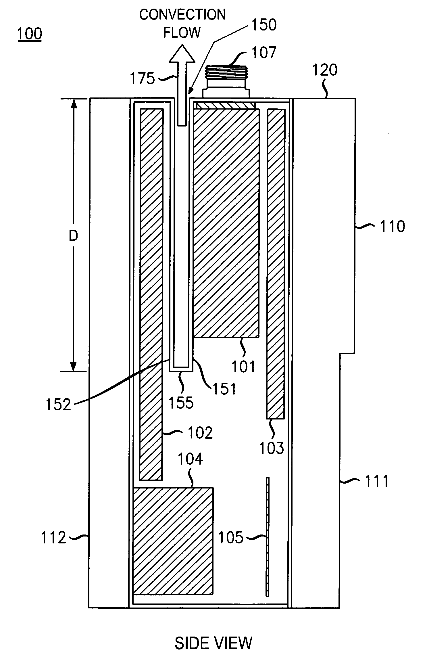
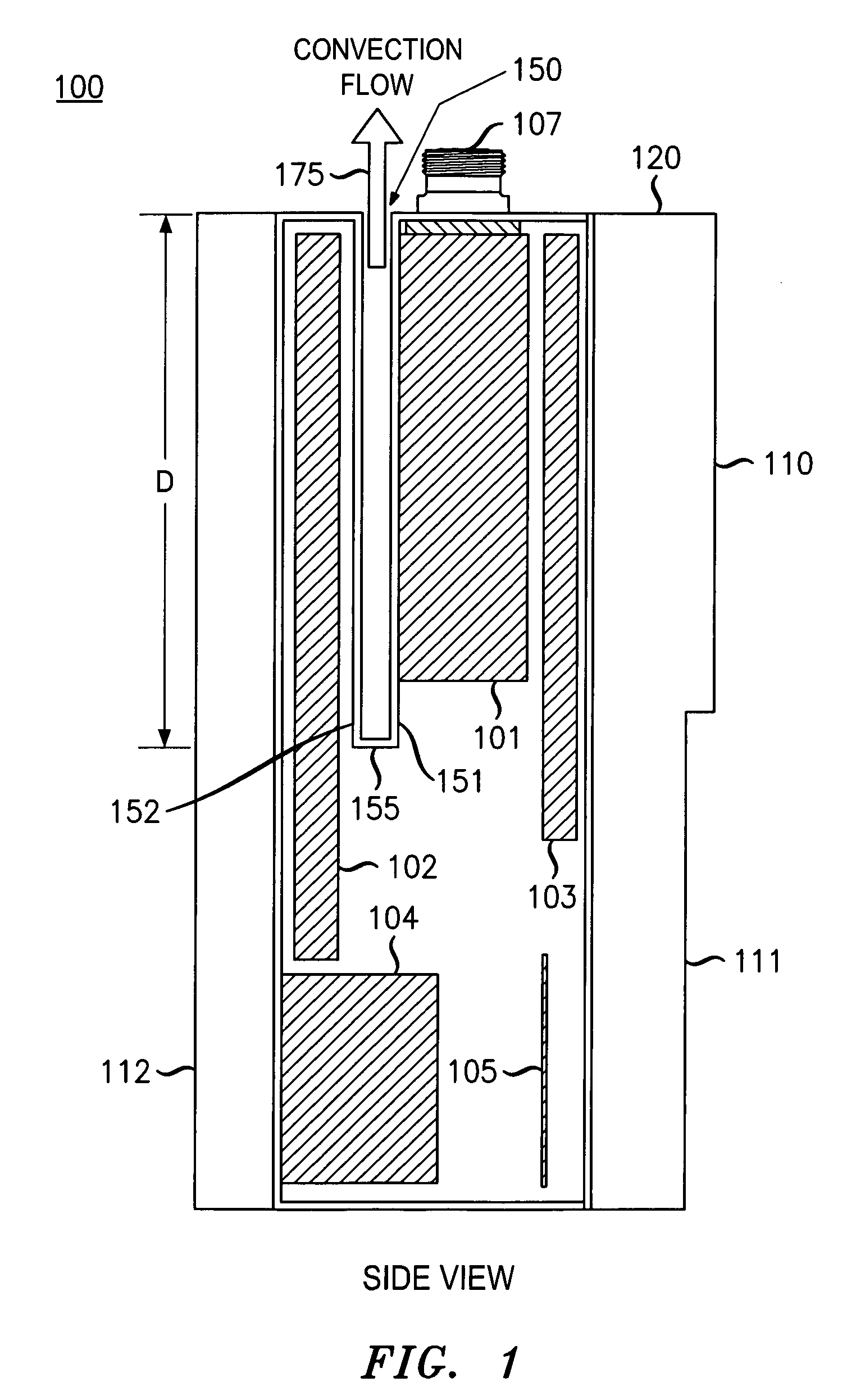
[0022]While the present disclosure is described, at least in some portions, in the context of telecommunications applications (e.g., a wireless base station), these examples are strictly meant to be illustrative only and not limiting in any way. In particular, the features related to the cooling arrangement described herein can be used in other non-telecommunications applications that include electronic, computer, and / or other equipment and components. Furthermore, the use of terminology such as equipment assembly, cabinet, enclosure, shelf, rack, bay, and so on, is not meant to be limiting. Rather, these terms may have equivalency and interchangeability in some contexts or, alternatively, simply illustrate the many different types of equipment housing configurations that can benefit from the cooling arrangement described herein.

[0023]FIG. 1 shows a side view of an equipment assembly 100 (with a side panel nominally removed) according to one illustrative embodiment. Equipment assemb...


PUM


Abstract

An equipment assembly includes a core cooling slot to manage thermal effects brought about by the generation of heat from components therein. The cooling slot is positioned within the equipment assembly so that only air that is external to the equipment assembly passes through the cooling slot to provide external convection-based cooling for components in a core section inside the equipment assembly. The cooling slot also acts as a thermal barrier for redistributing heat generated by the one or more components inside the equipment assembly.

Description

BACKGROUND[0001]1. Technical Field[0002]The invention relates generally to equipment assemblies that contain computer or electronic components and the like and, more specifically, to managing thermal effects within such equipment assemblies resulting from the generation of heat by those components.[0003]2. Discussion of the Art[0004]This section introduces aspects that may be helpful to facilitating a better understanding of the invention. Accordingly, the statements in this section are to be read in this manner and are not to be construed as admissions about what is prior art or what is not prior art.[0005]Equipment assemblies such as cabinets, enclosures, racks, frames, and the like for supporting or otherwise housing computer and other electronic equipment are known. Electronic components mounted within these equipment assemblies tend to generate heat that needs to be dissipated or otherwise mitigated in order to maintain proper operating conditions, to prevent damage to equipmen...

Claims


Application Information

Patent Timeline
IPC IPC(8): H05K7/20
CPCH05K7/20127H05K7/20518H05K7/20409
Inventor AKALANNE, LUCIUS CHIDIBATTEN, MARK VIVIAN
Owner ALCATEL-LUCENT USA INC
Why Eureka
Try Eureka